Temperature monitoring system for the entire region of environment

a temperature monitoring system and environment technology, applied in the direction of instruments, dynamo-electric converter control, optical radiation measurement, etc., can solve the problems of increasing the temperature of objects, indicating potential fire hazards, and increasing the cost of fabricating, so as to increase the practical value

Inactive Publication Date: 2012-06-19
LI LUNG TSAI
View PDF3 Cites 0 Cited by
  • Summary
  • Abstract
  • Description
  • Claims
  • Application Information

AI Technical Summary

Benefits of technology

[0008]The temperature monitoring system for the entire region of environment according to the present invention essentially comprises a multielement thermopile (TP) connected to a AD converter (ADC) which is linked with the first microcontroller (MCU), and then the first MCU is further connected to the stepping motor for vertical motion control, the stepping motor for horizontal motion control, and several microswitches. Further, the first MCU and the second MCU is linked together and the second MCU is linked with the monitoring apparatus. Accordingly, it is possible to identify a hot spot occurring in electrical heating equipment or a smoldering source hidden in upholstery. Thus, it is suitable for on-line and long-term temperature monitoring and it can detect indoor temperature through wireless sensor network application. In case of extremely high temperature, detection by the system can help to take proper measures or actions as early as possible so as further to prevent the fire from taking place. It can increase more practical value in the integral embodiment and usage thereof.

Problems solved by technology

Any unusual increase in the temperature of an object indicates a potential fire hazard.
The complicated mechanism results in the surging of fabricating cost.
Moreover, it can perform only one spot measurement so that this will cause inconvenience in implementation.
Thus, it has less convenience in the integral implementation and usage thereof.

Method used


Image

  • Temperature monitoring system for the entire region of environment
  • Temperature monitoring system for the entire region of environment
  • Temperature monitoring system for the entire region of environment

Examples


Embodiment Construction

[0014]The objects, the technical contents and the expected effectiveness of the present invention will become more apparent from the detailed description of the preferred embodiment in conjunction with the accompanying drawings.

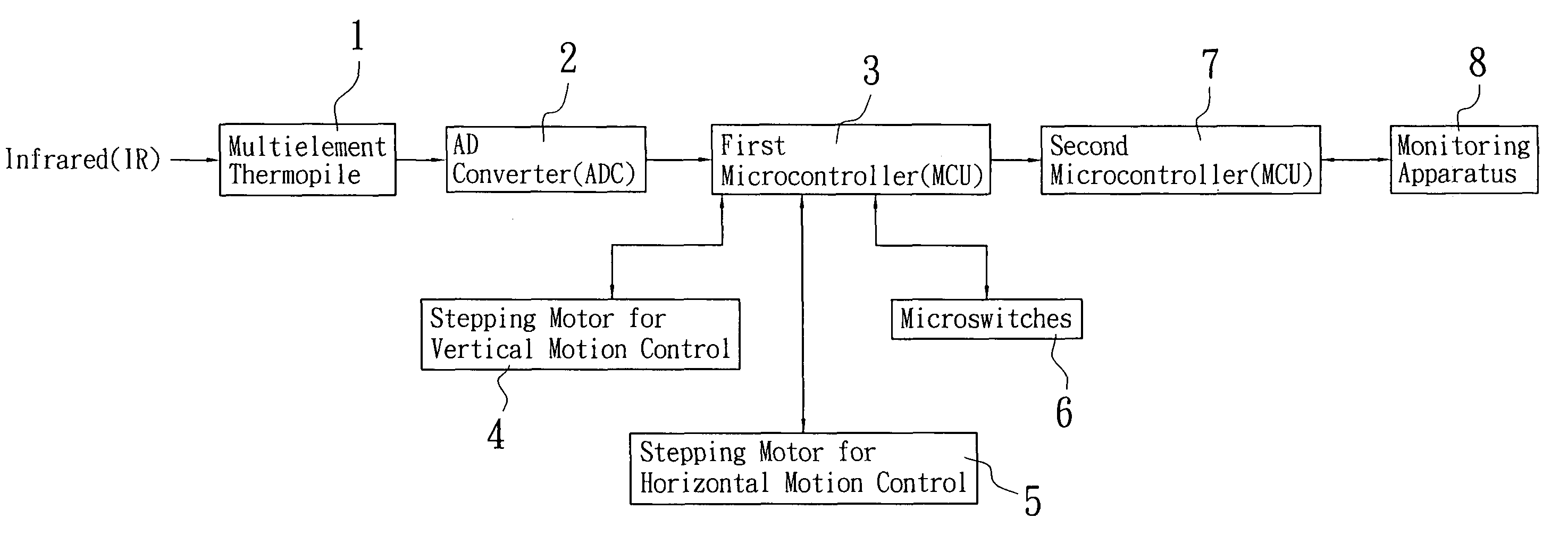
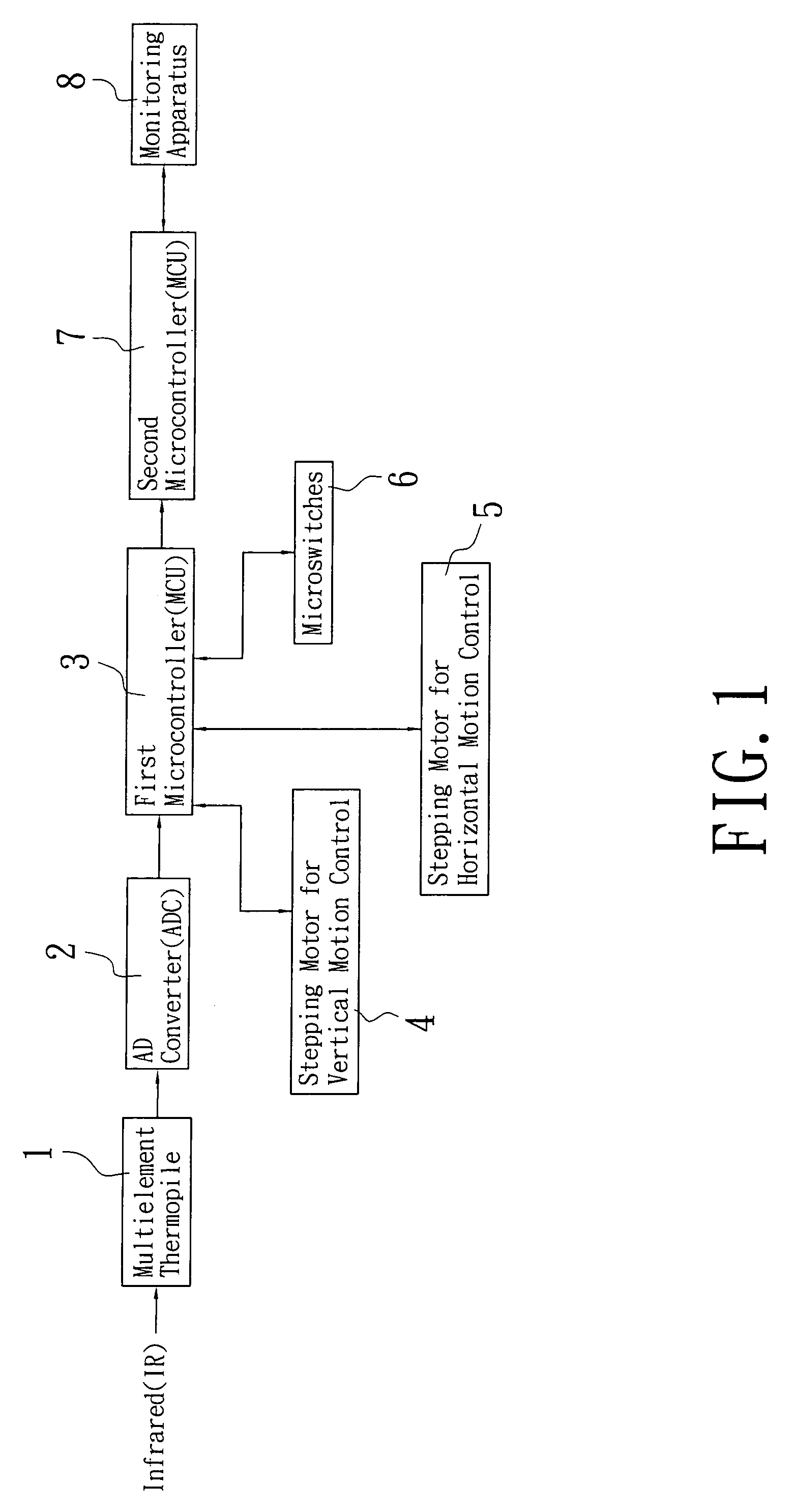
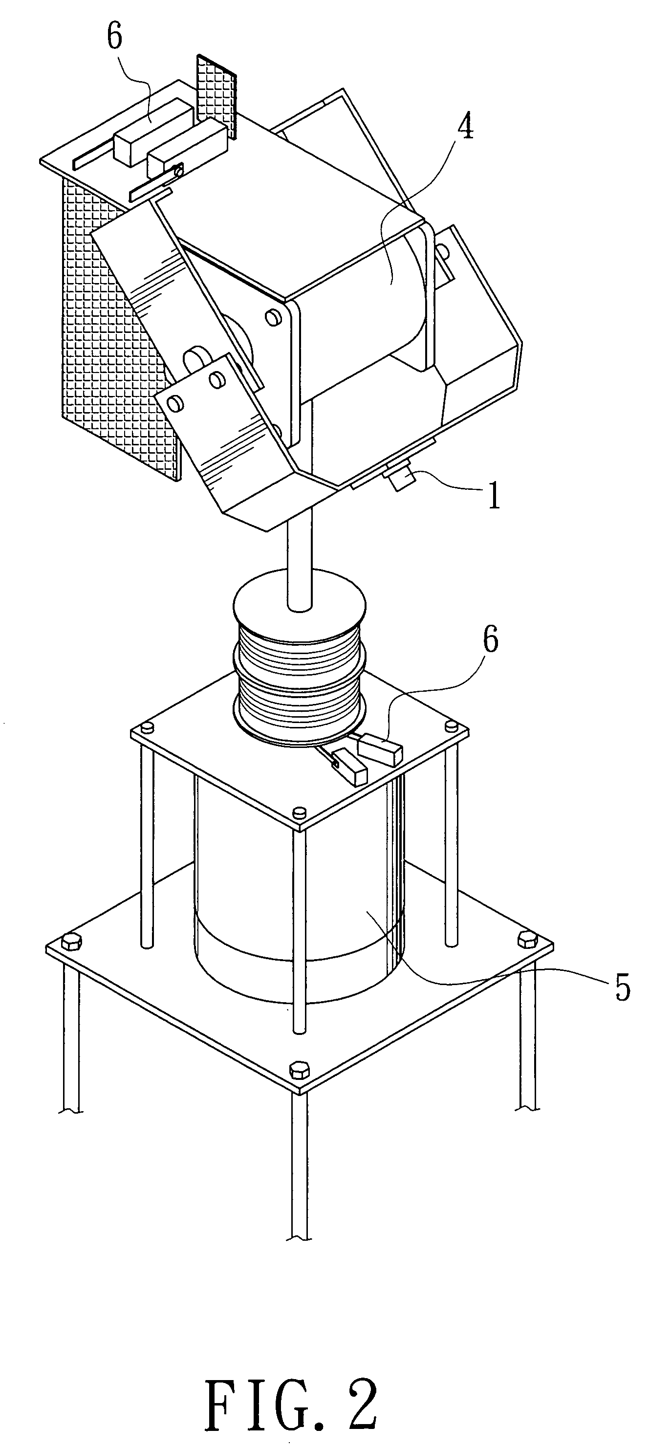
[0015]FIG. 1 is a block diagram showing the structure of the present invention, FIG. 2 is a schematic view showing the structure of the present invention. As shown in the figures, this invention essentially consists of a multielement thermopile (1) connected to a AD converter (ADC) (2) which is linked with the first microcontroller (MCU) (3), and then the first MCU (3) is further connected to the stepping motor (4) for vertical motion control, the stepping motor (5) for horizontal motion control, and several microswitches (6); further, the first MCU (3) is connected to the second MCU (7) by an RS-232 interface and the second MCU (7) is linked with the monitoring apparatus (8) by an RS-232 interface or by wireless mode, wherein:

[0016]The multielement TP (1) ca...


PUM


Abstract

A temperature monitoring system consists of a multielement thermopile, an analog-to-digital converter (ADC), first and second microcontrollers (MCUs), a first stepping motor, a second stepping motor, a plurality of microswitches and a monitoring apparatus. The multielement thermopile is connected to the ADC linked with the first MCU, and the first MCU is further connected to the first stepping motor with microswitches for vertical motion control, and the second stepping motor with microswitches for horizontal motion control. At the same time the first MCU can be connected to the second MCU and the second MCU is linked with the monitoring apparatus. A hot spot occurring in electrical heating equipment or a smoldering source hidden in upholstery can be identified and proper measures can be performed, in case of extremely high temperature, so as further to prevent a fire.

Description

BACKGROUND OF THE INVENTION[0001]1. Field of the invention[0002]The present invention relates to a temperature monitoring system for the entire region of environment, particularly to a novel temperature monitoring system for the entire region of environment, which can monitor a hot spot occurring in electrical heating equipment or a smoldering source hidden in upholstery to take proper measures or actions as early as possible, in case of extremely high temperature, so as further to prevent the fire from taking place. It can increase more practical value in the integral implementation and usage thereof.[0003]2. Brief Description of the Prior Art[0004]The temperature of a fire varies gradually during initial stages of its breakout. Hence, a smoldering source generally goes unnoticed as wooden material is being warmed. Any unusual increase in the temperature of an object indicates a potential fire hazard. Therefore, long-term detection of variations in temperatures of indoor environmen...

Claims


Application Information

Patent Timeline
Patent Type & Authority Patents(United States)
IPC IPC(8): H02P8/00
CPCG01J5/02G01J5/025G01J5/04G01J5/047G01J5/06G01J5/089G01J5/07
Inventor LI, LUNG-TSAI
Owner LI LUNG TSAI
Why Eureka
Try Eureka