

Dome shaped spring and switch
a dome-shaped spring and switch technology, applied in the direction of contacts, contact surface shape/structure, multiple contacts formed in one plate/layer, etc., can solve the problem of not being able to obtain clicking action, and achieve the effect of clear obtaining clicking action
- Summary
- Abstract
- Description
- Claims
- Application Information
AI Technical Summary
Benefits of technology
Problems solved by technology
Method used
Image


Examples
first modification
[0076]The first modification of the above described embodiment is described with reference to FIG. 8. FIG. 8 shows a cross sectional view of the configuration of the switch 10 of the present modification.
[0077]The switch 1 of the above described embodiment is a configuration including a dome shaped spring 2 including a projected shape in a direction opposite to the pushing direction of the operator. On the other hand, the switch 10 of the modification includes a dome shaped spring 2B including a projecting shape in the same direction as the pushing direction of the operator.
[0078]As shown in FIG. 8, the switch 10 includes a dome shaped spring 2B, substrates 3A and 3B, and fixed contacts 4A, 5A and 6A. The dome shaped spring 2B is a contact spring including a metal conductor such as stainless steel in a dome shape where the neutral surface is an aspherical shape similar to the dome shaped spring 2. The shape of the planar surface of the dome shaped spring 2B is circular. The center p...
second modification
[0083]The second modification of the above described embodiment is described with reference to FIG. 9A to FIG. 11B. FIG. 9A shows a planar view of a configuration of a dome shaped spring 2C of the present modification. FIG. 9B shows a cross sectional view of a configuration of the dome shaped spring 2C. FIG. 10A shows a planar view of a configuration of a dome shaped spring 2D of the present modification. FIG. 10B shows a side view of the configuration of the dome shaped spring 2D. FIG. 11A shows a planar view of a configuration of a dome shaped spring 2E of the present modification. FIG. 11B shows a cross sectional view of a configuration of the dome shaped spring 2E.
[0084]The switch 1 of the above described embodiment is a configuration including the dome shaped spring 2 where the shape of the planar surface is circular. Instead of the dome shaped spring 2, the switch of the present modification is a configuration including dome shaped spring 2C, 2D or 2E where a portion of the do...
example 1
[0090]A switch 30 as a first example of the switch 1 of the present embodiment is described with reference to FIG. 12. FIG. 12 shows a cross sectional view of the configuration of the switch 30 of the present embodiment.
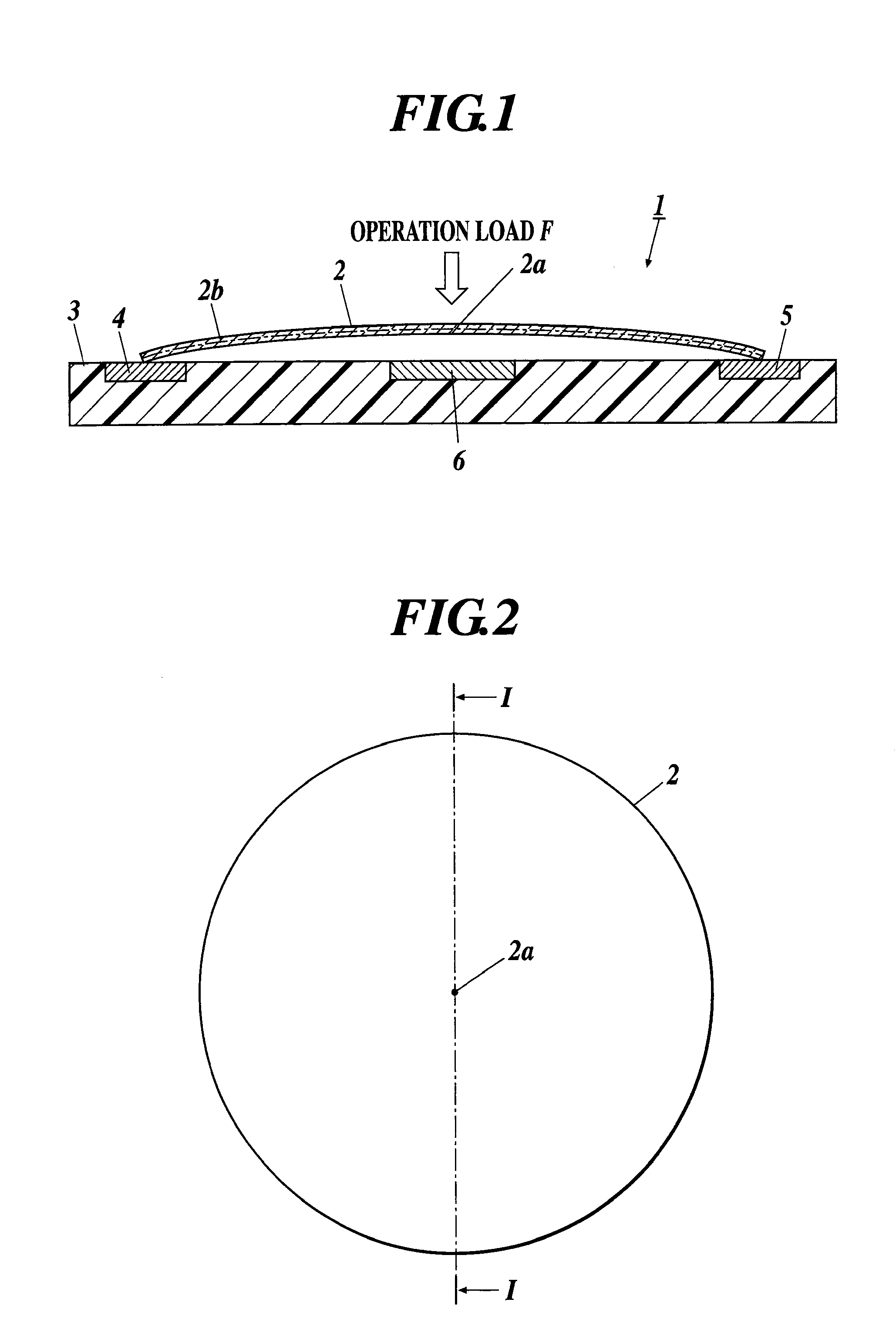
[0091]The switch 30 is a push button switch provided on an operation section, etc. in a portable device, etc. The switch 30 includes a dome shaped spring 2, a substrate 3C, fixed contacts 4C, 5C and 6C, an operation button 7 and a switch case 8. The substrate 3C and fixed contacts 4C, 5C and 6C correspond to the substrate 3 and fixed contacts 4, 5 and 6 respectively. Below, the same reference numerals are applied to the members which are the same as the embodiment, and the description is omitted.
[0092]The substrate 3C is a substrate including glass-epoxy resin, etc. The fixed contacts 4C, 5C and 6C, which are to be connected to the dome shaped spring 2, are placed on the substrate 3C. The fixed contacts 4C, 5C and 6C are electrical contacts including metal conductors...
PUM
 Abstract
Description
Claims
Application Information