Apparatus and method for tracking movement of a target

a technology of a target and an apparatus, applied in the field of head tracking, can solve the problems of affecting the quality of images, and affecting the presence of moving biological tissu

Inactive Publication Date: 2013-03-05
BOARD OF RGT THE UNIV OF TEXAS SYST +1
View PDF31 Cites 28 Cited by
  • Summary
  • Abstract
  • Description
  • Claims
  • Application Information

AI Technical Summary

Benefits of technology

[0029]The present invention includes improvements to the field of tracking patient movement in an MRI application. An apparatus and method are taught to track the movement of a patient's head during medical imaging scanning using optical technology. Feedback control of the gradient and / or radiofrequency magnetic fields can provide real time correction of imaging data.
[0035]One embodiment of the instant invention is a system that is taught used in conjunction within an MRI machine that uses a predetermined pattern placed or projected onto a patient's head to track movement of a patient during an MRI scan. Optical systems incorporating structured light and a processor record the position and movement of the pattern and are able to perform mathematical analysis of the pattern to determine the positional shift of the patient. Weighted averages, Fourier transforms, Hadamard matrices and cross-correlation of data related to X-Y translation, rotation and scaling of the image of the pattern are used to analyze movement of the patient's head. Feedback related to the movement is provided to the MRI machine that allows for adjustments in focusing coils for real time tracking of the patient's movements during the MRI procedure. As a result, the MRI procedure becomes more accurate as it is adjusted for the patient's movements.

Problems solved by technology

With conventional anatomic MR imaging, the presence of moving biological tissue is problematic.
The tissue produces image artifacts, degrades the quality of the images, and complicates the interpretation of MR images.
In addition, as BOLD imaging is typically coupled with a repetitive behavioral task (e. g., passive sensory, cognitive, or sensorimotor task) to localize BOLD signals in the vicinity of neurons of interest, there is significant potential for fMRI to be confounded by the presence of small head motions.
Random head motion decreases the statistical power with which brain activity can be inferred, whereas task-correlated motion cannot be easily separated from the fMRI signal due to neuronal activity, resulting in spurious and inaccurate images of brain activation.
In addition, head motion can cause mis-registration between neuroanatomical MR and fMR images that are acquired in the same examination session.
An analogous problem exists for aligning anatomical and functional MR images performed on different days.
Perhaps the most complicated scenario involves combining use of virtual reality (VR) technology with fMRI, to determine brain activity associated with VR tasks for assessment and rehabilitation of impaired brain function.
High-spatial resolution is a basic requirement of 3D brain imaging data for patients with neurological disease, and motion artifacts a consequence of movement during scanning pose a significant problem.
If a patient does not stay completely still during MR neuroimaging, the quality of the MR scan will be compromised.
The absence of beam-hardening artifacts from bone allows complex approaches to anatomic regions that may be difficult or impossible with other imaging techniques such as conventional CT.
However, the non-magnetic environment required by the scanner, and the strong magnetic radiofrequency and quasi-static fields generated by the scanner hardware require the use of specialized instruments.
Prior art attempts at tracking motion using cross-correlation and other simple distance measurement techniques have not been highly effective where signal intensities vary either within images, between images, or both.
One of the problems with this invention is that the application and implementation of this methodology has proven difficult.
However, unlike the present invention, the system disclosed by Nevo is not capable of position tracking when imaging gradients are inactive, nor is it capable of measurements outside the sensitive volume of the imaging gradients.
As in anatomical MRI, these schemes remain an incomplete solution to the problem and the search for improved motion suppression continues.
This problem is particularly manifest in specific patient populations (e.g., dementia, immediate post-acute phase of stroke).
Furthermore, image-based coregistration algorithms suffer from methodological limitations.
Consequently, the resulting co-registered images still can suffer from residual motion contamination that impairs the ability to interpret brain activity.
There are several drawbacks of this approach, including the requirement of a second “tracking” component that must be calibrated with a dummy object, the position ambiguity due to the configuration of this approach, and the inherent limitation of the resolution provided by this approach.
However, resolutions provided by the Jakab invention are not as precise as is possible.

Method used


Image

  • Apparatus and method for tracking movement of a target
  • Apparatus and method for tracking movement of a target
  • Apparatus and method for tracking movement of a target

Examples


Embodiment Construction

[0055]While the making and using of various embodiments of the present invention are discussed in detail below, it should be appreciated that the present invention provides many applicable inventive concepts which can be embodied in a wide variety of specific contexts. The specific embodiments described herein are merely illustrative of specific ways to make and use the invention and do not delimit the scope of the invention.

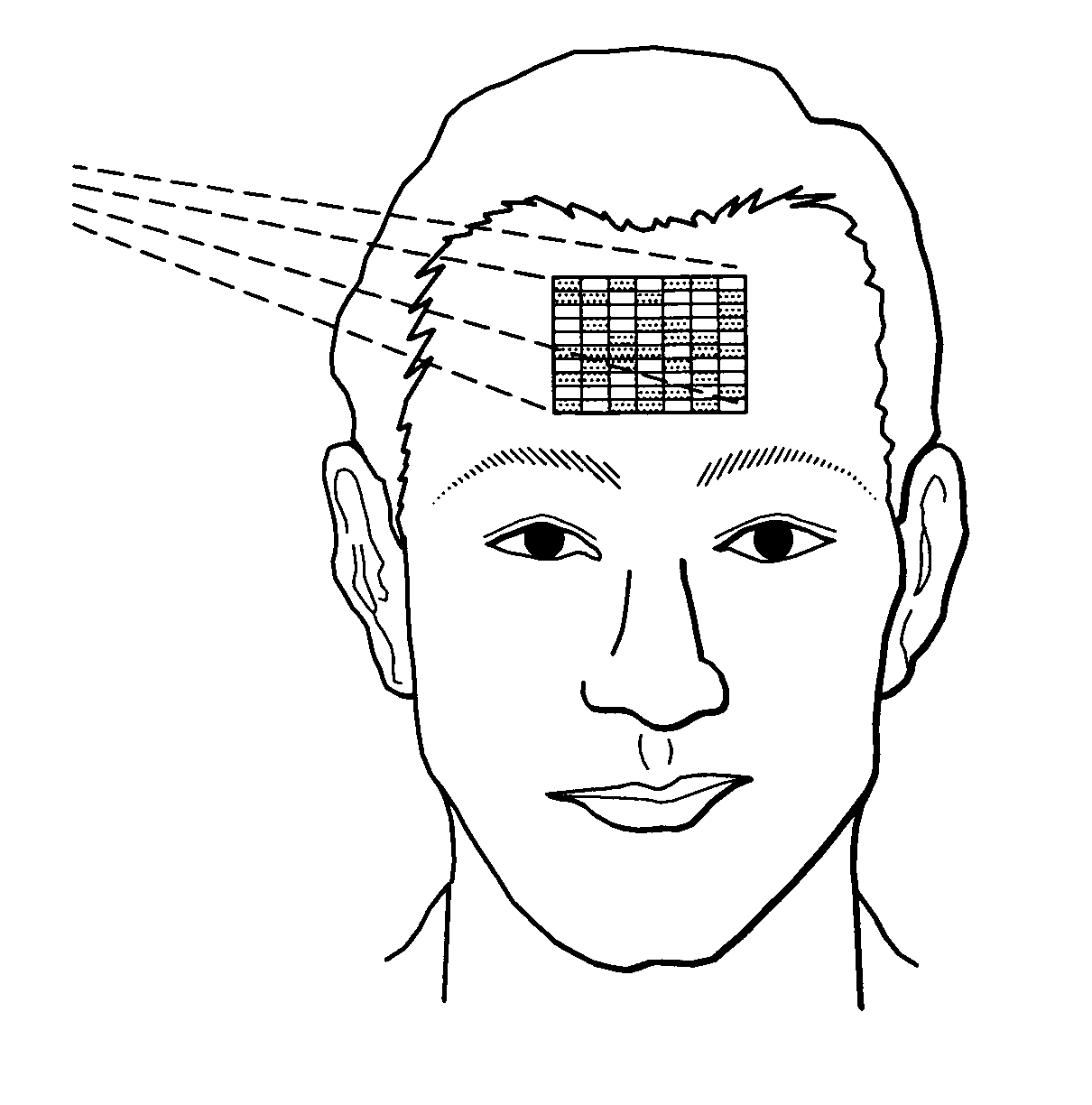
[0056]In one embodiment of the instant invention is a system that is used in conjunction within an MRI machine that uses a predetermined pattern placed or projected onto a patient's head to track movement of a patient during an MRI scan. Optical systems record the position and movement of the pattern and are able to perform mathematical analysis of the pattern to determine the positional shift of the patient.

[0057]In this preferred embodiment, light is projected onto a target that reflects some of the light into an optical receiver. One of the innovations of the...


PUM


Abstract

The present invention discloses an apparatus and method to track the movement of a target. One embodiment tracks the movement of the patient during medical imaging scanning using optical technology. Optical systems record the position and movement of the target and provide inputs to a processor. The processor is capable of performing mathematical analysis of the movement of the target to determine the positional shift of the patient. Weighted averages, phase correlation, Fourier-Mellin algorithms, and cross-correlation of data related to X-Y translation are used to calculate movement of the target subject. Feedback related to the movement is provided to the medical imaging scanning machine which allows for adjustments in focusing coils for real time tracking of the patient's movements during the procedure. As a result, the medical image scanning procedure becomes more accurate as it is adjusted for the patient's movements.

Description

CROSS REFERENCE TO RELATED APPLICATIONS[0001]This application is a Continuation claiming priority benefit from U.S. patent application Ser. No. 12 / 152,951, filed May 19, 2008 now U.S. Pat. No. 7,977,942 entitled “Apparatus and Method for Tracking Movement of a Target” which claims priority benefit from U.S. patent application Ser. No. 11 / 282,046, now U.S. Pat. No. 7,498,811 issued on Mar. 3, 2009.TECHNICAL FIELD OF THE INVENTION[0002]The present invention relates, in general, to the field of motion tracking, and in particular to head tracking in a magnetic resonance imaging application. In particular the invention teaches an apparatus and method to track the movement of a target in three-dimensional space during medical imaging scanning using optical technology. The invention further comprises an apparatus and method to use the head tracking data to control the magnetic field gradients and / or radio frequency fields of the magnetic resonance imaging instrument thereby maintaining act...

Claims


Application Information

Patent Timeline
Patent Type & Authority Patents(United States)
IPC IPC(8): G01V3/00
CPCG01R33/28G01R33/4806G01R33/56509G01V8/20G01R33/543
Inventor MACFARLANE, DUNCAN L.BRIGGS, RICHARDZAREMBA, ANDREI A.WHITE, KEITH D.
Owner BOARD OF RGT THE UNIV OF TEXAS SYST
Why Eureka
Try Eureka