Airbag apparatus for vehicle

a technology for airbags and vehicles, which is applied in the direction of vehicle components, pedestrian/occupant safety arrangements, vehicular safety arrangments, etc., can solve the problems of seat passenger injuries, passenger head injuries, and passenger head injuries, and achieve smooth and reliable airbag deployment, shorten the time it takes for the airbag cushion to be completely deployed, and smooth flow

Active Publication Date: 2013-03-12
HYUNDAI MOTOR CO LTD +2
View PDF49 Cites 17 Cited by
  • Summary
  • Abstract
  • Description
  • Claims
  • Application Information

AI Technical Summary

Benefits of technology

[0010]Various aspects of the present invention are directed to provide an airbag apparatus for a vehicle which is configured such that gas smoothly flows in an airbag cushion so that when a vehicle collision occurs, the airbag cushion can effectively protect a passenger.
[0018]First, gas can smoothly flow in the front portion of an airbag cushion. Therefore, the time it takes the airbag cushion to be completely deployed is shortened, which makes the deployment of the airbag smooth and reliable.
[0019]Second, the airbag cushion is supported by a headliner in a reverse right-triangular shape. Therefore, the cushion can effectively absorb impact applied to the passenger and thus maintain the passenger in a stable position.
[0020]Third, when the airbag cushion is deployed, a depressed head support portion of the airbag cushion can maintain the head of the passenger in a stable position. Hence, the cushion can more effectively absorb the impact applied to the passenger when the cushion is deploying.
[0021]Fourth, the present invention can reduce impact applied to the head of the passenger when the airbag cushion is supporting the position of the passenger, thus minimizing injury to the passenger, and fundamentally preventing the neck of the passenger from being bent by the inflation pressure of the airbag cushion.

Problems solved by technology

However, when a vehicle is involved in a frontal collision, a rear seat passenger that is not wearing a safety belt may injure his / her head as a result of colliding with the head of a passenger in the front seat or with the back of the front seat.
As a result, the head or neck of the passenger 40 may be injured by the cushion 30 that is inflated at high pressure.

Method used


Image

  • Airbag apparatus for vehicle
  • Airbag apparatus for vehicle
  • Airbag apparatus for vehicle

Examples


Embodiment Construction

[0030]Reference will now be made in detail to various embodiments of the present invention(s), examples of which are illustrated in the accompanying drawings and described below. While the invention(s) will be described in conjunction with exemplary embodiments, it will be understood that present description is not intended to limit the invention(s) to those exemplary embodiments. On the contrary, the invention(s) is / are intended to cover not only the exemplary embodiments, but also various alternatives, modifications, equivalents and other embodiments, which may be included within the spirit and scope of the invention as defined by the appended claims.

[0031]Hereinafter, an exemplary embodiment of the present invention will be described in detail with reference to the attached drawings.

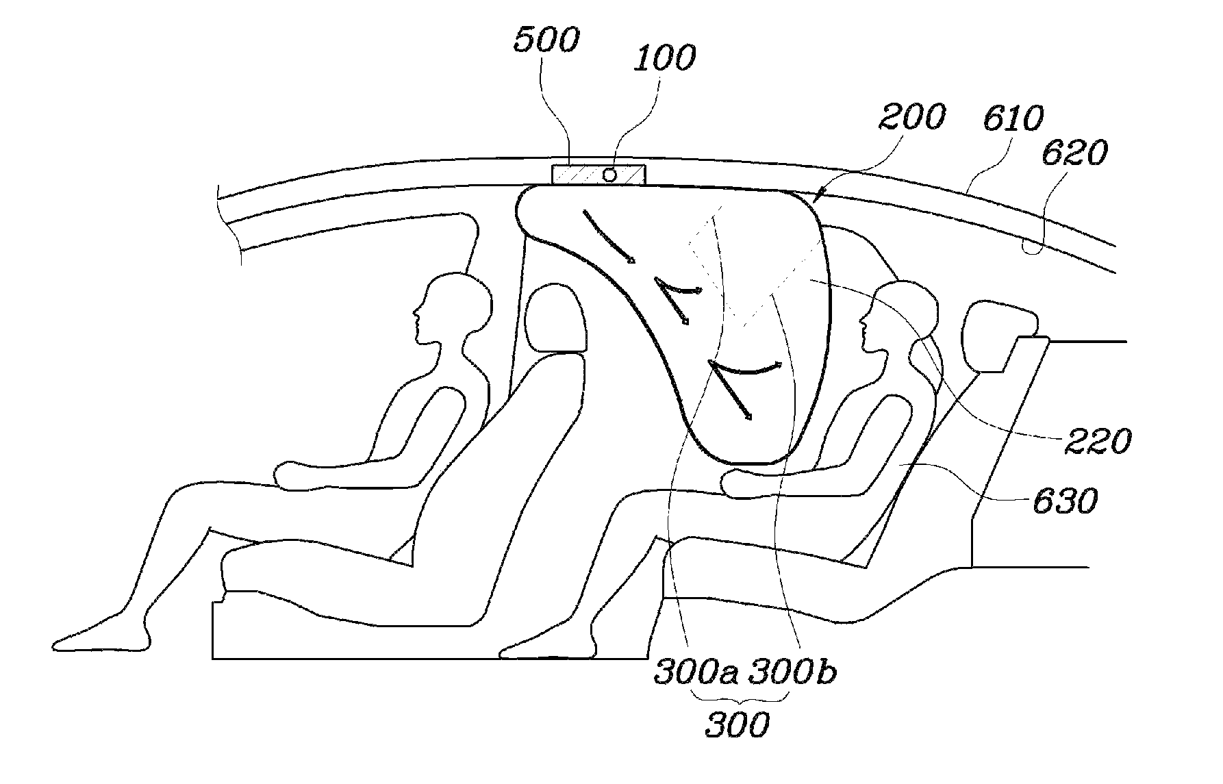
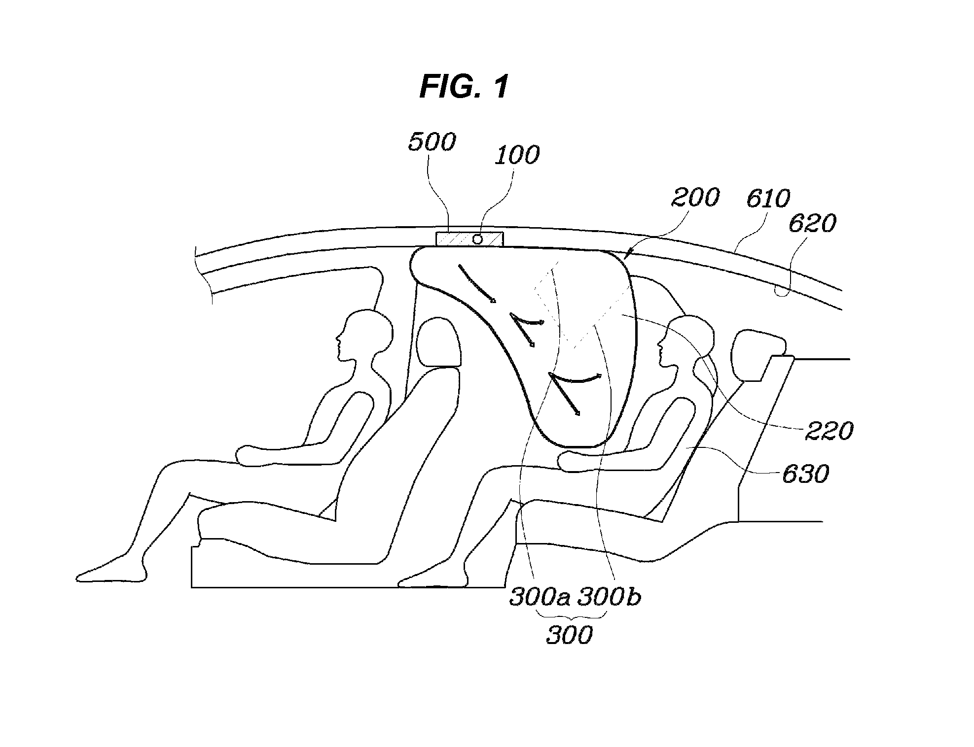
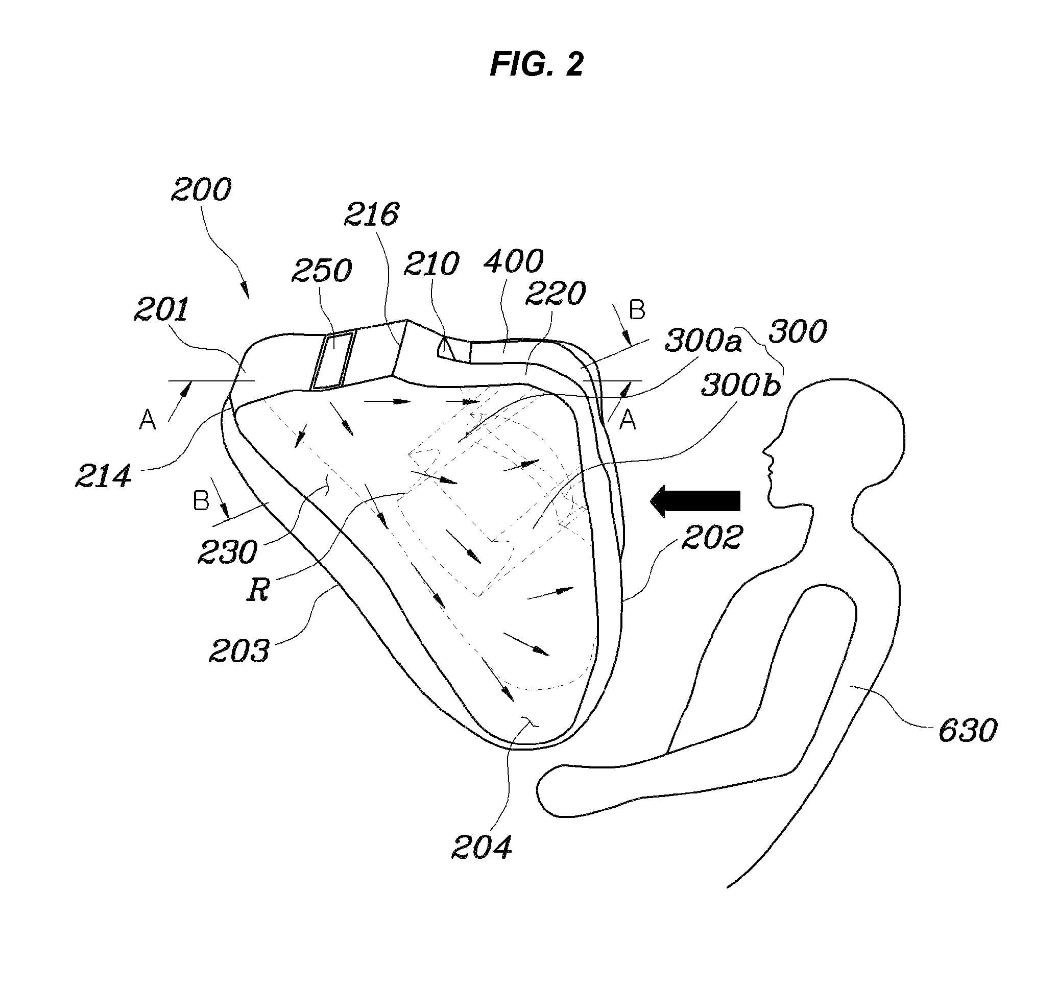
[0032]As shown in FIGS. 1 and 2, in an airbag apparatus according to an exemplary embodiment of the present invention, a gas path 230 is formed in a front portion of an airbag cushion 200 such that th...


PUM


Abstract

An airbag apparatus for a vehicle may include an inflator, and an airbag cushion having a depressed head support portion formed in a rear portion of the airbag cushion so that when the airbag cushion may be deployed by gas supplied from the inflator, the head support portion receives a head of a passenger, and shoulder support portions protruding from lateral sides of the head support portion in a rearward direction and forming a space between the shoulder support portions to have the head support portion therebetween when the airbag cushion may be deployed, and a support tether provided in the airbag cushion and extending in a transverse direction across the shoulder support portions such that a gas path may be defined in a front portion of the airbag cushion below the support tether, the gas path guiding the gas downwards.

Description

CROSS-REFERENCE TO RELATED APPLICATIONS[0001]The present application claims priority to Korean Patent Application No. 10-2010-0083881 filed on Aug. 30, 2010, the entire contents of which is incorporated herein for all purposes by this reference.BACKGROUND OF THE INVENTION[0002]1. Field of the Invention[0003]The present invention relates generally to airbag apparatuses for vehicles and, more particularly, to an airbag apparatus which is installed in a roof of a vehicle so that when a vehicle collision occurs, an airbag is deployed to protect a passenger.[0004]2. Description of Related Art[0005]Hitherto, development of airbag apparatuses for vehicles has been focused on protecting front seat passengers.[0006]However, when a vehicle is involved in a frontal collision, a rear seat passenger that is not wearing a safety belt may injure his / her head as a result of colliding with the head of a passenger in the front seat or with the back of the front seat. Taking into account the fact that...

Claims


Application Information

Patent Timeline
Patent Type & Authority Patents(United States)
IPC IPC(8): B60R21/214B60R21/2338
CPCB60R21/214B60R21/231B60R21/2338B60R2021/23386B60R2021/23153
Inventor CHOI, JUN YEOLYOO, WAN DONGGO, JAE MAN
Owner HYUNDAI MOTOR CO LTD
Why Eureka
Try Eureka