Floating fastener

a technology of floating fasteners and screw members, which is applied in the direction of threaded fasteners, screws, bolts, etc., can solve the problems of user injury, screw member and/or pin missing somewhere when removed from board members, and user may have to spend a lot of time, so as to facilitate mounting and dismounting and avoid missing components.

Inactive Publication Date: 2013-03-12
HANWIT PRECISION IND LTD
View PDF5 Cites 19 Cited by
  • Summary
  • Abstract
  • Description
  • Claims
  • Application Information

AI Technical Summary

Benefits of technology

[0006]The present invention has been accomplished under the circumstances in view. It is therefore an object of the present invention to provide a floating fastener, which facilitates mounting and dismounting without causing obstruction, and avoids missing of component parts.

Problems solved by technology

When fastening or unfastening a screw member or a pin, the user may be injured by the tip of the screw member or pin accidentally.
Further, screw members and / or pins may be missed somewhere when removed from board members.
Further, if different sizes of screw members and / or pins are stored in one same storage device or place, the user may have to spend a lot of time to pick up the desired size of screw members and / or pins from the storage device for application.

Method used


Image

  • Floating fastener
  • Floating fastener
  • Floating fastener

Examples


Embodiment Construction

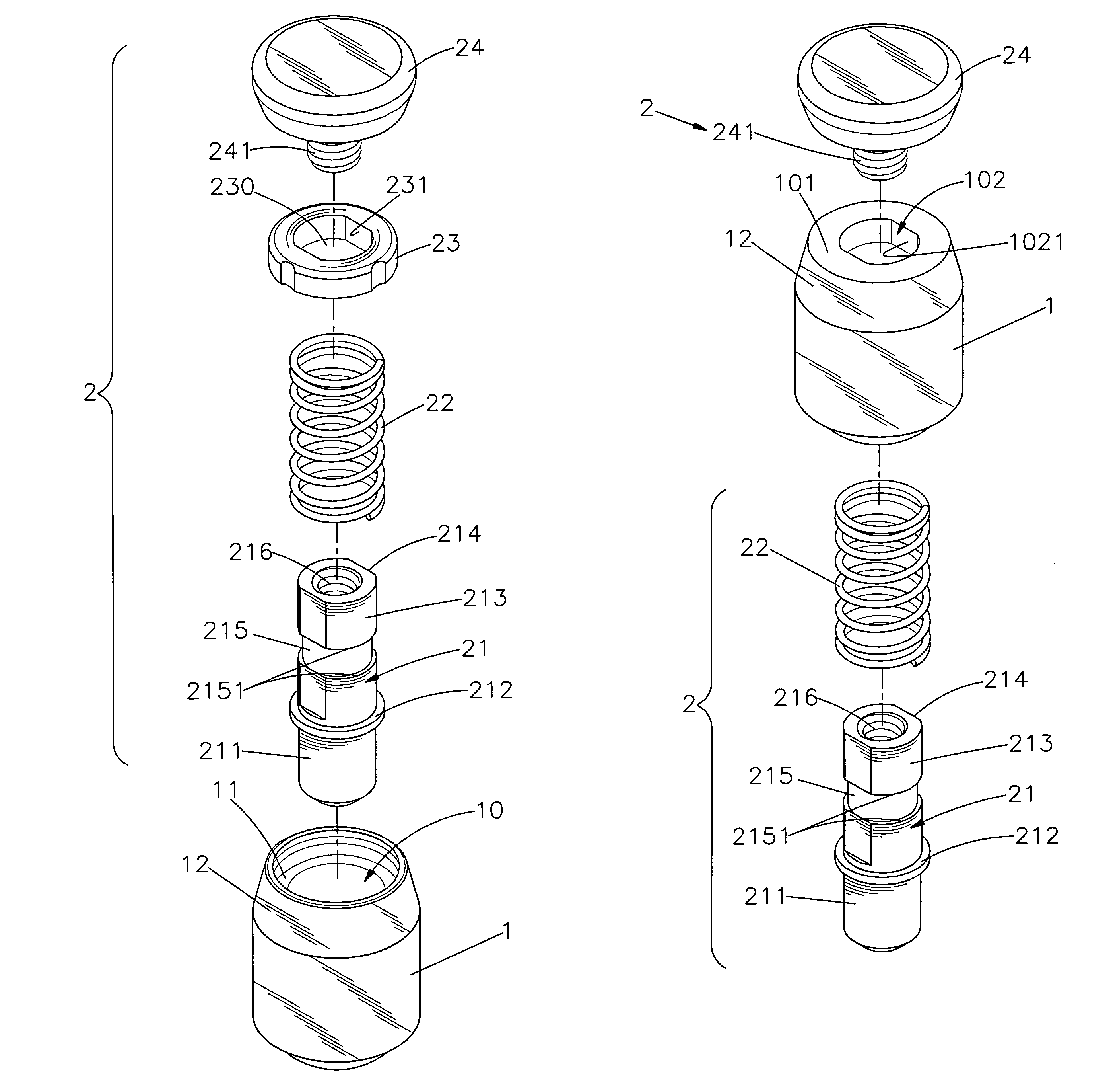
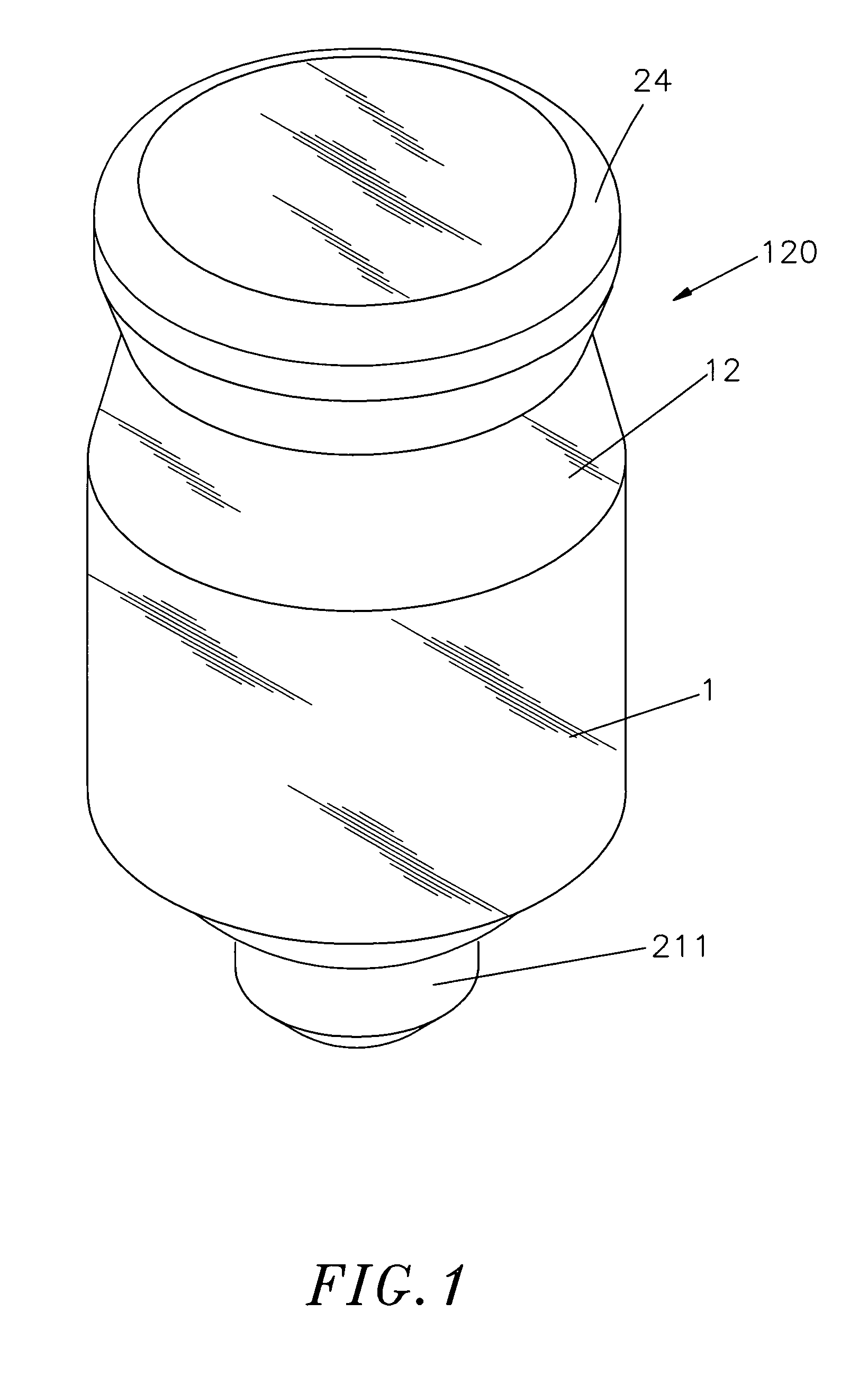
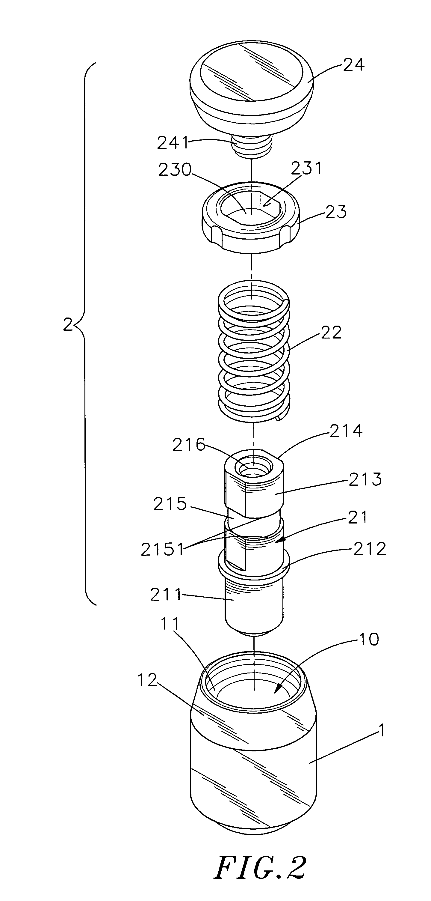
[0021]Referring to FIGS. 1˜3, a floating fastener in accordance with a first embodiment of the present invention is shown comprising a base member 1 and a locking rod set 2.

[0022]The base member 1 has a tapered end portion 12 located on one end thereof, namely, the top end, an accommodation chamber 11 surrounded by the tapered end portion 12, a tubular mounting neck 13 axially extended from an opposite end thereof, namely, the bottom end, an axial hole 10 axially defined therein in communication between the accommodation chamber 11 and the inside space of the tubular mounting neck 13, and a shoulder 14 located on the inside between the axial hole 10 and the tubular mounting neck 13. The tubular mounting neck 13 has an outer diameter smaller than the outer diameter of the periphery of the base member 1.

[0023]The locking rod set 2 includes a locking rod 21, a spring member 22, a limiter block 23 and a knob 24. The locking rod 21 has an elongated rod body 213, a locking tip 211 axially...


PUM


Abstract

A floating fastener includes a base member, a limiter block fastened to one end of the base member and defining an elliptical constraint hole, a locking rod inserted through the non-circular constraint hole of the limiter block and having an annular groove extending around the periphery of the non-circular rod body thereof, a spring member sleeved onto the locking rod and stopped between a stop flange of the locking rod and the limiter block, and a knob fastened to one end of the locking rod and disposed outside the base member and operable to move the locking rod axially relative to the base member and to rotate the locking rod, when the locking rod is moved to the elevation where the annular groove of the locking rod is kept in the non-circular constraint hole of the limiter block, between a constrained position where the locking rod is stopped by the limiter block from axial movement relative to the base member and a released position where the locking rod is released from the constraint of the limiter block and movable axially relative to the base member.

Description

BACKGROUND OF THE INVENTION[0001]1. Field of the Invention[0002]The present invention relates to floating fasteners for joining metal board members and more particularly, to a floating fastener including a base member and a locking rod set consisting of a locking rod, a spring member, a limiter block and a knob, which facilitates mounting and dismounting without causing obstruction, and avoids missing of component parts.[0003]2. Description of the Related Art[0004]Screw members and pins are commonly used in our daily life to temporarily locking movable devices in position. For example, when moving a sliding box or a board member of a machine case to a predetermined position, a screw member or pin may be used to temporarily lock the sliding box or board member in position for allowing the user to perform certain tasks. Further, screw members and / or pins are intensively used in desk computers, notebook computers, industrial computers, workstations to detachably fasten board members to...

Claims


Application Information

Patent Timeline
Patent Type & Authority Patents(United States)
IPC IPC(8): F16B21/18
CPCF16B5/0208F16B5/0266
Inventor CHIU, MING-CHUNG
Owner HANWIT PRECISION IND LTD
Why Eureka
Try Eureka