
Walking assistance device

a technology of assistance device and walking aid, which is applied in the field of walking assistance device, can solve the problems of difficulty in opening his/her, and achieve the effect of facilitating the user to open his/her legs apar

Active Publication Date: 2013-03-12
HONDA MOTOR CO LTD
View PDF16 Cites 17 Cited by
  • Summary
  • Abstract
  • Description
  • Claims
  • Application Information

AI Technical Summary

Benefits of technology

The present invention is about a walking assistance device that includes a narrower ankle joint swinging range in the rolling direction. The ankle joint is designed to have a greater swingable range to the abduction side, making it easier for the user to open their legs apart. The joint shaft member is inclined towards the abduction side, which widen the swingable range of the ankle joint to the adduction side when the device is upright. This allows the user to open their legs wider without compromising the proper motion of the ankle joint. Additionally, when the user turns their foot in the yaw direction, the ankle joint follows their motion without any variation on the swingable range. Overall, this invention improves the user's experience and makes the device more efficient in assisting the user's walking.

Problems solved by technology

If a coupling mechanism, which is limited in a swinging range, like a spherical joint is used for an ankle joint, the limitation in the swinging range may cause a difficulty in making a motion of opening his / her legs apart with the Leg links extended laterally.

Method used


Image

  • Walking assistance device
  • Walking assistance device
  • Walking assistance device

Examples


Embodiment Construction

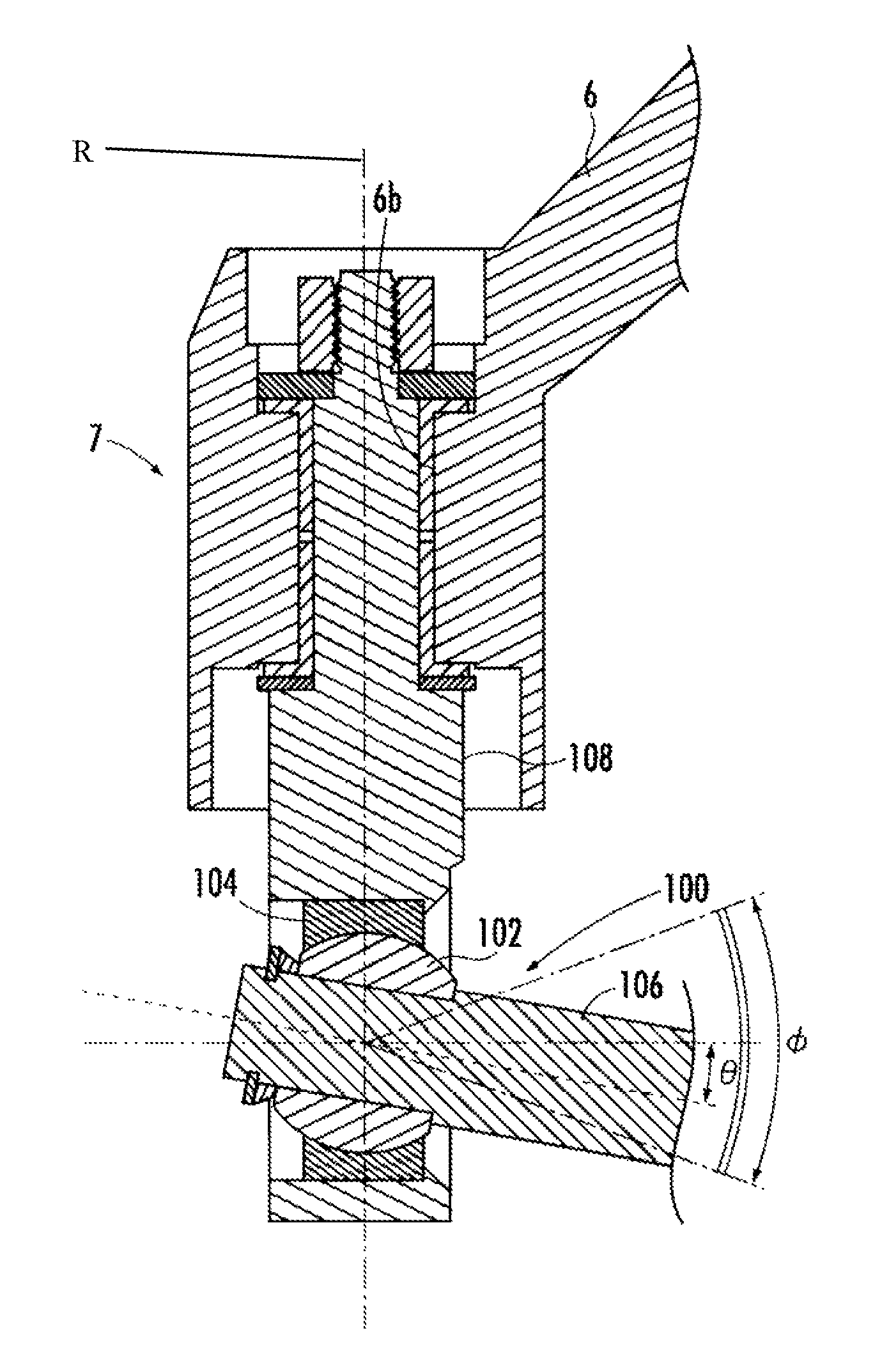
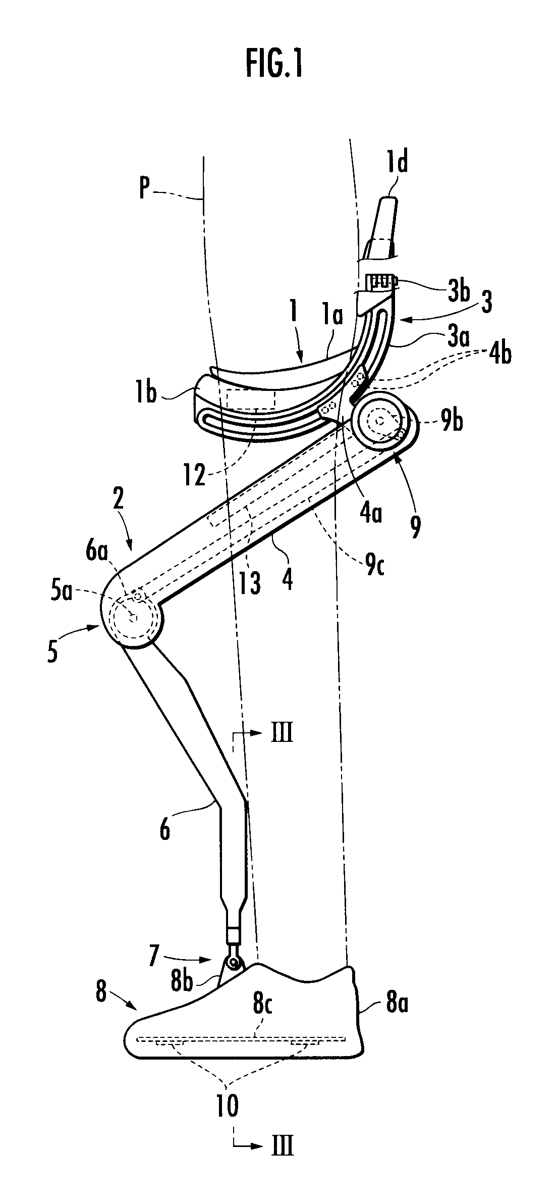
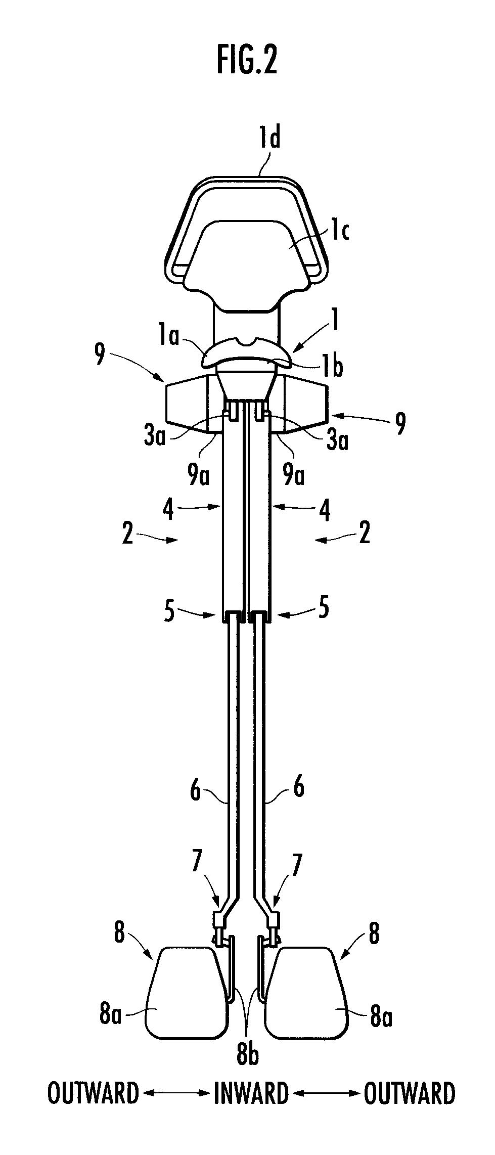
[0020]The following will describe an embodiment of a walking assistance device of the present invention with reference to FIG. 1 to FIG. 3. As illustrated in FIG. 1 and FIG. 2, the walking assistance device has a seating member 1 on which a user P sits in a straddling manner and a pair of right and left leg links 2 and 2 supporting the seating member 1 from below.

[0021]Each of the leg links 2 is formed of a bendable link having a first link member 4, which is connected to a first joint 3 provided on the seating member 1, and a second link member 6, which is connected to a lower end of the first link member 4 through a rotary second joint 5 at the lower end of the first link member 4. Further, a ground contact member 8 to be attached to each of right and left feet of the user is connected to a lower end of the second link member 6 through an ankle joint 7.

[0022]Each of the leg links 2 is further provided with a drive source 9 for the second joint 5. The second joint 5 is rotationally...


PUM


Abstract

A walking assistance device having an ankle joint limited in a swingable range in a rolling direction, enabling a user to open his / her legs apart more easily. The walking assistance device includes a seating member 1, a pair of leg links 2 and 2 which support the seating member 1 from below, and a ground contact member 8 connected to each leg link 2 through an ankle joint 7. The ankle joint 7 has a coupling mechanism 100 which includes a joint shaft member 106 and a retaining portion which swingably retains the joint shaft member 106 in the rolling direction in a predetermined range φ. The joint shaft member 106 is inclined to an abduction side in the rolling direction from the middle position of the predetermined range φ in which the joint shaft member is swingable in the rolling direction when the walking assistance device is in an upright state.

Description

BACKGROUND OF THE INVENTION[0001]1. Field of the Invention[0002]The present invention relates to a walking assistance device which assists a user in walking.[0003]2. Description of the Related Art[0004]Hitherto, as this type of walking assistance device, there has been known a walking assistance device which includes a seating member on which a user sits in a straddling manner and a pair of leg links supporting the seating member from below, wherein the leg links receive at least a part of the weight of the user through the seating member to reduce load acting on a leg or legs of the user, thereby assisting the user in walking (refer to, for example, Japanese Patent Application Laid-Open No. 2007-054616).[0005]Further, there has been known another walking assistance device in which a ground contact member to be attached to each of the feet of the user is connected to each leg link through an ankle joint, which is formed of a spherical joint as a coupling mechanism limited in a swing...

Claims


Application Information

Patent Timeline
Patent Type & Authority Patents(United States)
IPC IPC(8): A61H1/00
CPCA61H3/008A61H3/00A61H2201/1633A61H2201/5061A61H2201/5071A61H2201/1215A61H2201/1436A61H2201/1623A61H2201/1635A61H2201/1642A61H2201/165A61H2201/1671A61H2201/1676
Inventor ASHIHARA, JUNKUDOH, HIROSHIMATSUDA, HIROSHIKOSHIISHI, TAKESHIHIKI, YUTAKA
Owner HONDA MOTOR CO LTD
Learn More