Heat generating element and electric auxiliary heater for a motor vehicle with heat generating element

a technology of heat generating element and motor vehicle, which is applied in the direction of heater elements, resistors, air heaters, etc., can solve the problems of poor thermal efficiency of known heat generating elements, insufficient contact pressure, and poor conduction of heat generated by ptc elements to the outside, so as to achieve easy handling and installation

Inactive Publication Date: 2013-03-12
CATEM
View PDF22 Cites 3 Cited by
  • Summary
  • Abstract
  • Description
  • Claims
  • Application Information

AI Technical Summary

Benefits of technology

[0023]It showed to be particularly practical to embody both housing elements, i.e. the housing shell element and the shell counter element, as identical components which each have a U-shaped cross-section and grip the edge of a portion of the PTC heating element. In this case, the housing shell element and the shell counter element essentially have half the thickness of the PTC heating element. Each of the housing elements as shell element laterally encloses a portion of the PTC heating element. This embodiment offers the advantage that both housing elements can be manufactured in an identical mold. Moreover, merchandise management and storage as well as production logistics are facilitated as the housing is embodied by two identical components.
[0026]If the heat generating element according to the invention is arranged under spring pretension in a frame as part of a layer composition, for example according to EP 0 350 528, the adhesive sealing strip can join the two housing elements to form a unit which can be more easily handled and installed during assembly.

Problems solved by technology

Basically, in such generic heat generating elements, there is a problem in that a low transition resistance is to be provided by good mechanical contacting between the strip conductor and the PTC element, such that current feed to the heat generating element is possible without substantial heating at the phase interface to the PTC element.
This arrangement alone is not sufficient for developing sufficient contact pressure for pressing the strip conductors against the PTC element.
The known heat generating element is relatively passive, i.e. the conduction of heat generated by the PTC element to the outside is relatively poor.
The known heat generating element correspondingly has a poor thermal efficiency and reacts relatively slowly to changing thermal conditions.
This construction, however, involves the problem that in particular in operation of the heat generating element at high voltages, leakage currents migrating via the radiator elements and / or the frame cannot be prevented.
Moreover, the current-bearing parts at the outer side of the heat generating element are exposed, which is critical also for safety reasons.
The heating rod known from DE 28 04 749 also has the above mentioned disadvantage with respect to poor heat conduction, in this heating rod three generic heat generating elements being arranged at an angle of 120° offset to each other about a cylinder axis.
Such a construction is insufficient in particular in the convective dissipation of heat generated by the PTC element by air.

Method used


Image

  • Heat generating element and electric auxiliary heater for a motor vehicle with heat generating element
  • Heat generating element and electric auxiliary heater for a motor vehicle with heat generating element
  • Heat generating element and electric auxiliary heater for a motor vehicle with heat generating element

Examples


first embodiment

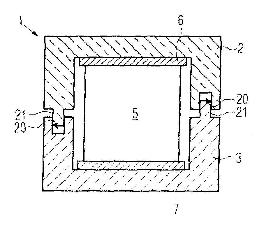
[0033]FIG. 1 shows a cross-sectional view of a heat generating element 1 which comprises two oblong U-shaped housing elements 2, 3 which are embodied each as sintered alumina components. The webs of each individual housing element 2, 3 situated opposite to each other are lying against each other at the front side with the interposition of a sealing strip 4. The thus created space which is electrically sealed at the circumference accommodates several PTC heating elements arranged one after the other in the longitudinal direction of the heat generating element 1 (across the drawing plane), here only one heating element 5 being shown.

[0034]Between the PTC heating element 5 and the two housing elements 2, 3, sheet metal strips 6, 7 are provided each as strip conductors for feeding the PTC heating elements 5 with current. As usual, the strip conductors can project from the housing elements 2, 3, at the front end thereof to there possibly project from the outer side of a frame surrounding...

second embodiment

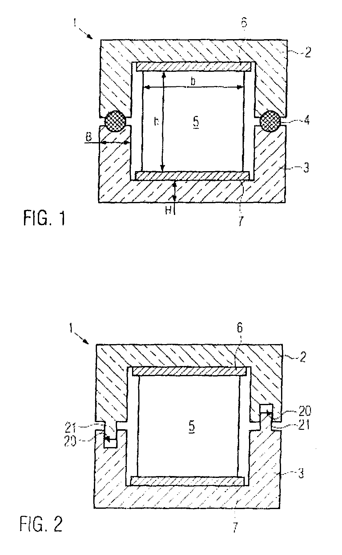
[0038]In FIG. 2, a cross-sectional view of a second embodiment is shown. Same components are designated with the same reference numerals with respect to the embodiment shown in FIG. 1.

[0039]The embodiment shown in FIG. 2, too, has two identical housing elements 2, 3 for facilitating production. One of the front sides of the respective housing elements 2 and 3 formed by the edges has a groove 20; a spring 21 projects from the other front side. The spring 21 of one of the housing elements 2, 3 is engaged with the complementarily formed groove 20 of the other housing element 3, 2, so that the interior of the housing 2, 3 is sealed. For this, it should be taken care that the width of the groove 20 is only slightly larger than the thickness of the spring 21. The depth of the groove 20 or the length of the spring 21 are selected such that, if PTC elements 5 are accommodated in the housing, these flatly lie against the sheet metal strips 6, 7, and that the housing elements 2, 3, in case of...


PUM


Abstract

A heat generating element for heating air in an electric auxiliary heater of a motor vehicle includes at least one PTC heating element and an insulating housing surrounding the PTC heating element as well as electric strip conductors lying against the PTC heating element at opposite sides. The housing is embodied in two parts with a housing shell element and a shell counter element which are lying against each other with the interposition of a sealing strip and sealingly surround the at least one PTC heating element. The present invention further relates to an electric auxiliary heater for a motor vehicle with a layer composition held in a frame, comprising the at least one heat generating element.

Description

BACKGROUND OF THE INVENTION[0001]1. Field of the Invention[0002]The present invention relates to a heat generating element having at least one PTC heating element and an insulated housing surrounding the PTC heating element as well as electric strip conductors lying against the PTC heating element at opposite sides.[0003]2. Description of the Related Art[0004]Such a heat generating element is known as part of an auxiliary heater for a motor vehicle, for example from EP 0 350 528. Other heat generating elements are known, for example, from DE 32 08 802, DE 30 46 995 or DE 28 04 749.[0005]Basically, in such generic heat generating elements, there is a problem in that a low transition resistance is to be provided by good mechanical contacting between the strip conductor and the PTC element, such that current feed to the heat generating element is possible without substantial heating at the phase interface to the PTC element. This requirement becomes in particular relevant if the heat g...

Claims


Application Information

Patent Timeline
Patent Type & Authority Patents(United States)
IPC IPC(8): B60L1/02
CPCH01C1/022H01C1/1406H01C7/02H05B3/50H05B2203/02F24H3/04H05B3/06H05B3/14
Inventor NIEDERER, MICHAELBOHLENDER, FRANZ
Owner CATEM
Why Eureka
Try Eureka