

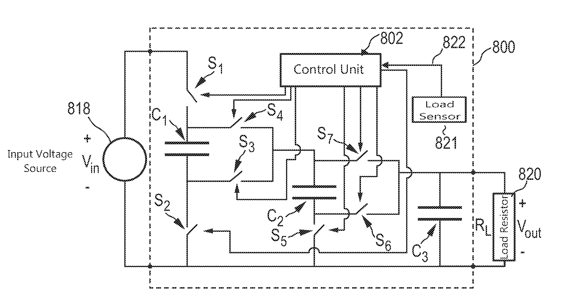
DC-to-DC converter comprising a reconfigurable capacitor unit
a capacitor unit and converter technology, applied in the direction of electric variable regulation, process and machine control, instruments, etc., can solve the problems of reducing the suitability of the present application and removing the benefit, so as to reduce the switching loss, minimize the output impedance, and minimize the effect of output impedan
- Summary
- Abstract
- Description
- Claims
- Application Information
AI Technical Summary
Benefits of technology
Problems solved by technology
Method used
Image

Examples
Embodiment Construction
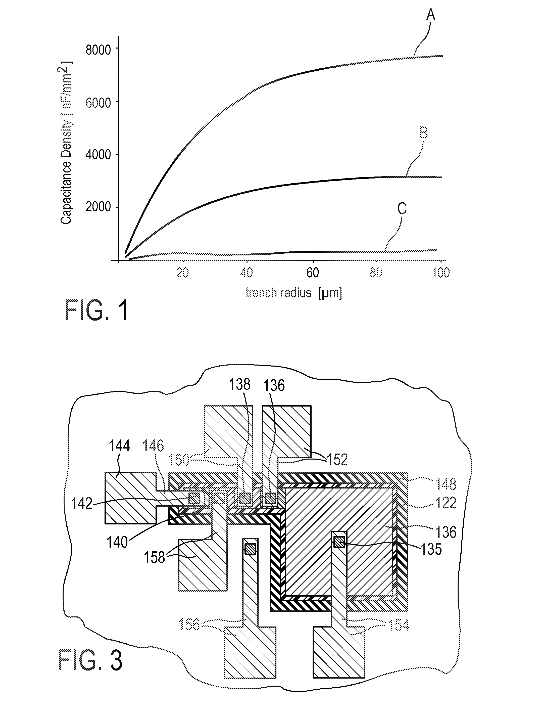
[0089]FIG. 1 is a diagram showing calculations of capacitance densities that can be achieved with a trench capacitor using multiple layer stacks. In the diagram the capacitance density in units of nF / mm2 (Nanofarad per square millimetre) is plotted as a function of a radius of a cylindrical trench, in which the trench capacitor is formed, in units of micrometer. The three curves A, B, and C shown were calculated for three different material combinations and processes that have values of a dielectric breakdown field, which values differ by a factor of 2. The breakdown field is considered as being proportional to the inverse of the square root of the relative dielectric constant of the dielectric material used for the dielectric layers of the trench capacitor. A constant breakdown voltage of the capacitor of 30 V was used as a constraint for all three material combinations and processes. An additional constraint was used for determining the respective metal thickness for a respective ...
PUM
 Abstract
Description
Claims
Application Information