
Vibration absorber for a vehicle suspension spring

a technology of vibration absorber and vehicle suspension spring, which is applied in the direction of shock absorber, wound spring, transportation and packaging, etc., can solve the problems of affecting the ride characteristics of the vehicle, moving the noise and vibration period to a less desirable place, and reducing the surge resonance sufficiently to reduce the surge resonance effect, noise reduction, and attenuation of vibration

Inactive Publication Date: 2013-03-19
GM GLOBAL TECH OPERATIONS LLC
View PDF18 Cites 5 Cited by
  • Summary
  • Abstract
  • Description
  • Claims
  • Application Information

AI Technical Summary

Benefits of technology

[0007]The absorber reduces noise and attenuates vibration transmitted into the passenger compartment by the suspension system without compromising ride quality or vehicle performance, or adjusting stiffness of the suspension spring.
[0009]The isolators damp the energy and reduce the amount of dynamic energy transmitted into the vehicle. The imbedded masses either shift the natural frequency of the coil spring to a more acceptable frequency or act as a tuned absorber that reduces the amplitude of displacement at the spring's natural frequency.

Problems solved by technology

Attempting to solve the concern by significantly changing the stiffness of the springs can negatively affect the ride characteristics of the vehicle, and simply moves the noise and vibration period to a less desirable place.
The coating has some damping effect, but not enough to significantly reduce a surge resonance.

Method used


Image

  • Vibration absorber for a vehicle suspension spring
  • Vibration absorber for a vehicle suspension spring
  • Vibration absorber for a vehicle suspension spring

Examples


Embodiment Construction

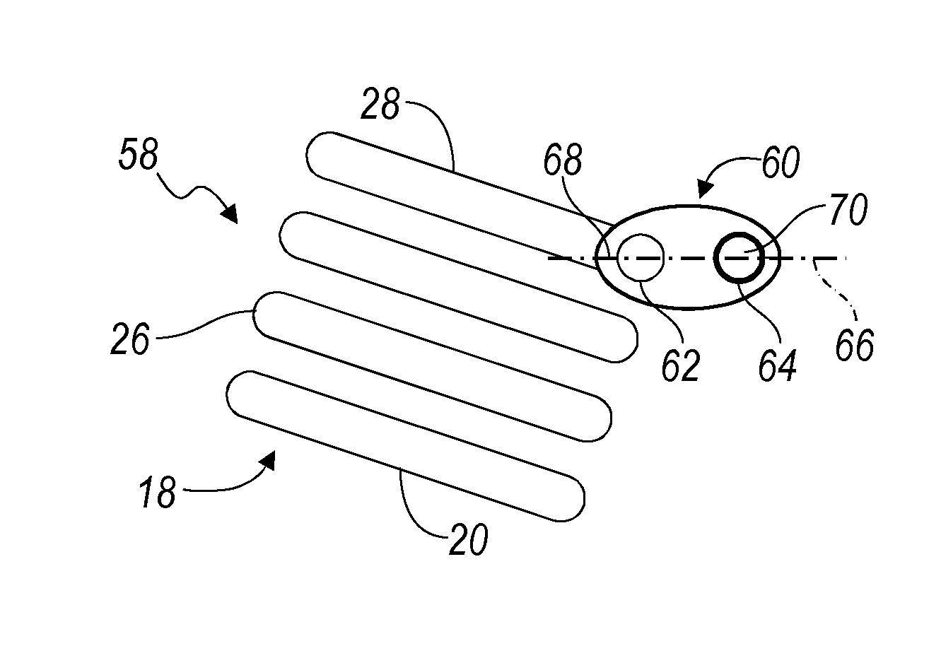
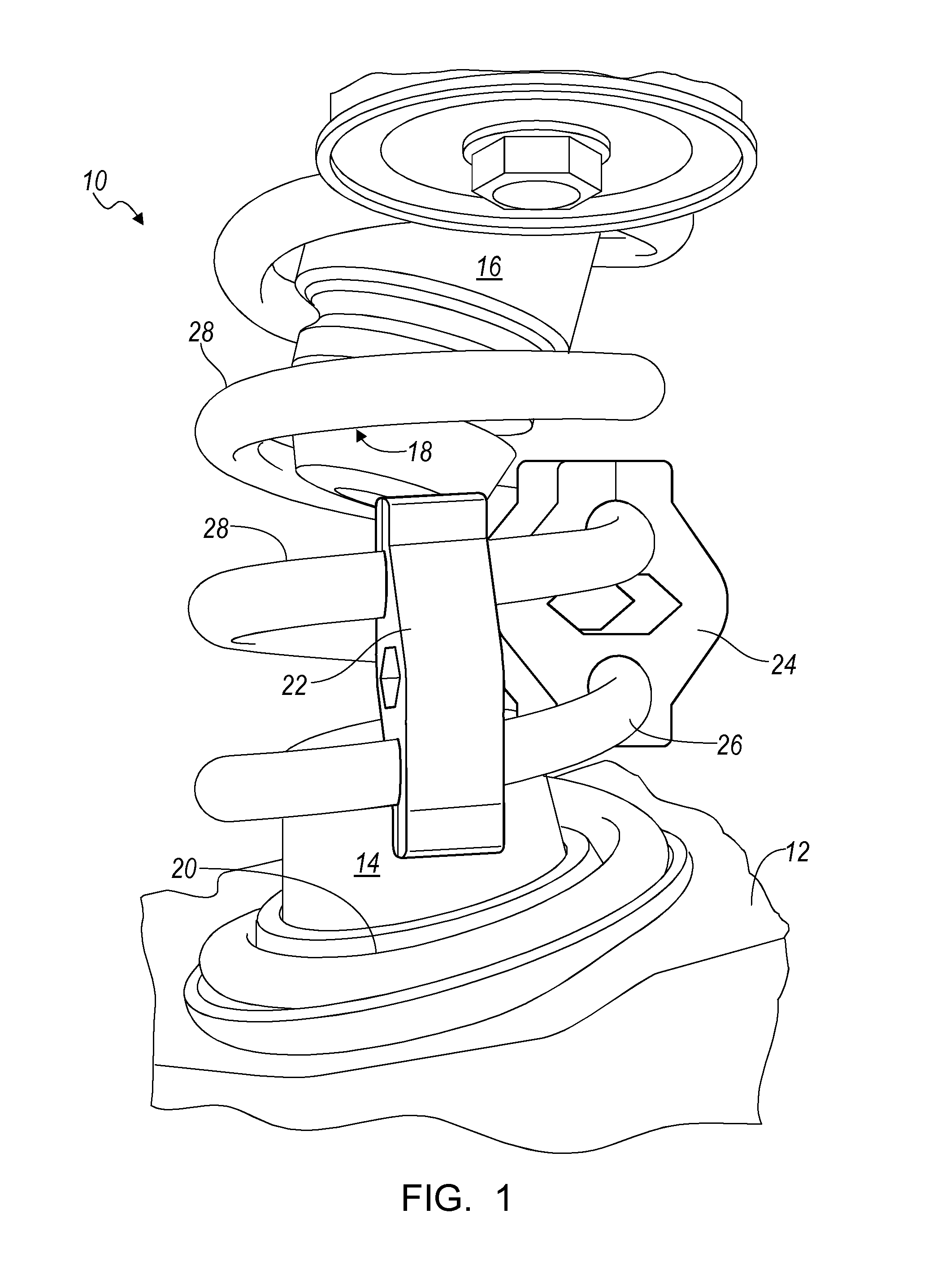
[0014]Referring now to the drawings, there is illustrated in FIG. 1 a portion of a vehicle suspension system 10, which includes a vehicle frame 12 formed with a boss 14 extending upward from the upper surface of the frame; a shock absorber strut 16 spaced from the boss and secured to the vehicle body; and a rear helical coiled compression spring 18 fitted over the boss and strut. The lowermost coil 20 of spring 18 contacts the upper surface of frame 12 and is located at the base of boss 14. Similarly, the uppermost coil of spring 18 contacts the lower surface of the body and is centered on the strut 16.

[0015]A dynamic vibration absorber added to the suspension system 10 includes first and second isolators 22, 24 secured to coils 26, 28 of the spring 18.

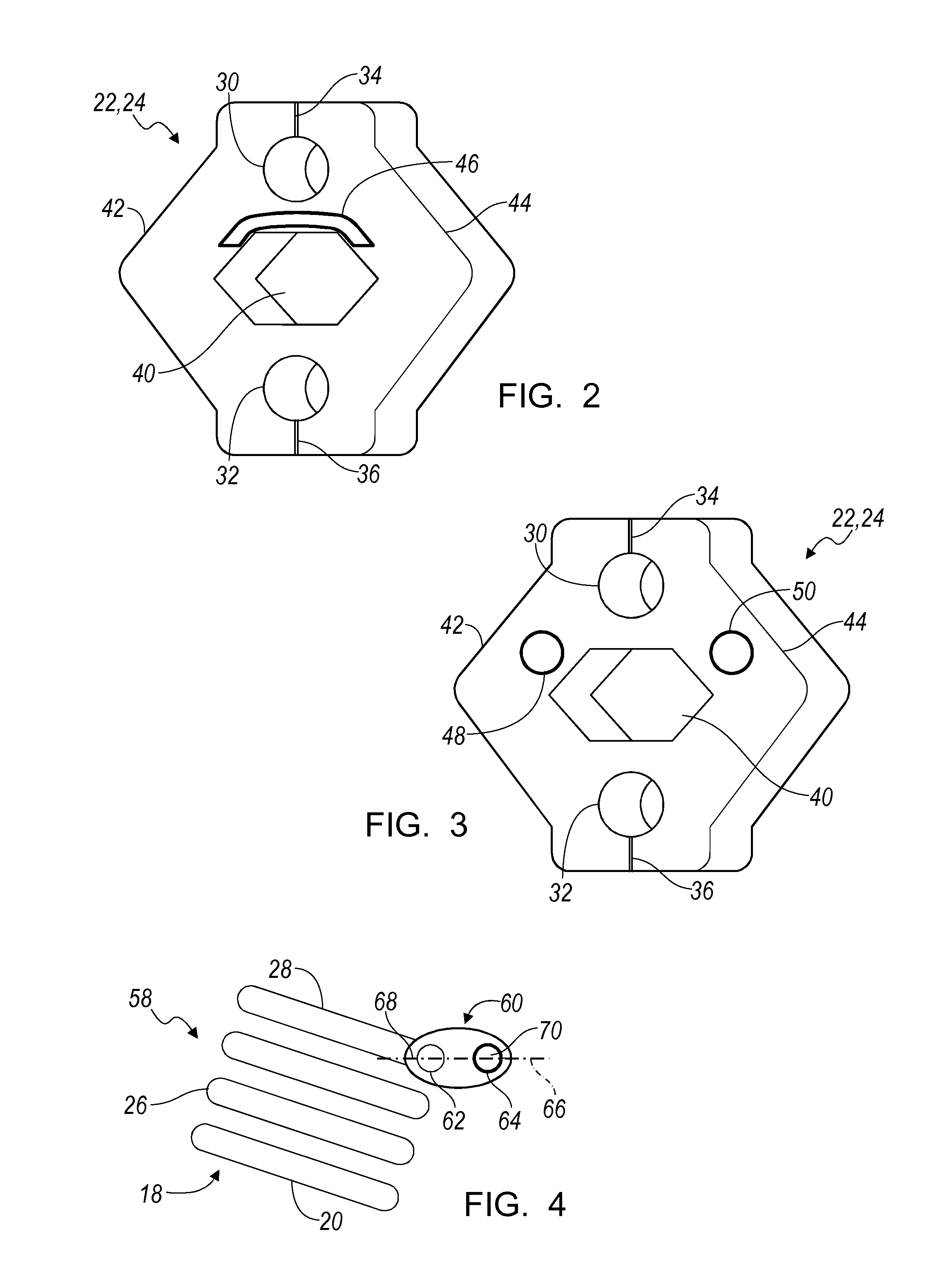
[0016]FIG. 2 shows that each isolator 22, 24 is formed with two circular holes 30, 32 sized to receive the coils 26, 28. Each isolator 22, 24 has a first slit 34 through its thickness and extending radially outward from the center of ...


PUM


Abstract

A dynamic vibration absorber for a vehicle suspension system includes a spring elastically supporting a vehicle body on a vehicle frame, the spring including multiple coils, an isolator secured to at least one of the coils, at least a portion of the isolator being elastically displaceable in response to movement of one of the coils, and a mass formed as unit with the isolator portion, and supported on the isolator for elastic movement.

Description

BACKGROUND OF INVENTION[0001]The present invention relates generally to an apparatus for reducing noise and vibration transmitted into the passenger compartment of a vehicle from the suspension system.[0002]Rear suspension coiled springs of a motor vehicle have a surge resonance that can be excited typically through a rear drive module and transmitted into the passenger compartment of the vehicle through the rear half-shafts and the rear suspension. Generally very little energy from the rear drive module is required to excite a steel spring at its resonant frequency, typically about 80 Hz. The energy is amplified at this frequency and transmitted into the vehicle where a ‘boom’ period is heard, producing noise during a vibration period.[0003]Attempting to solve the concern by significantly changing the stiffness of the springs can negatively affect the ride characteristics of the vehicle, and simply moves the noise and vibration period to a less desirable place.[0004]Dipping or coat...

Claims


Application Information

Patent Timeline
Patent Type & Authority Patents(United States)
IPC IPC(8): B60G11/14
CPCF16F1/13F16F7/108
Inventor STANFORTH, KYLE W.KLINE, STEVEN M.
Owner GM GLOBAL TECH OPERATIONS LLC
Learn More