Multistable shape-shifting surfaces

a technology of shape-shifting surfaces and surfaces, applied in the field of surfaces, can solve the problems of limited, albeit known, accuracy, model accuracy, and inability to accurately identify between flexure geometries and rigid-body mechanisms, and achieve the effect of identical to those produced more quickly

Inactive Publication Date: 2013-03-26
UNIV OF SOUTH FLORIDA
View PDF17 Cites 6 Cited by
  • Summary
  • Abstract
  • Description
  • Claims
  • Application Information

AI Technical Summary

Benefits of technology

[0022]The novel multistable shape-shifting surfaces disclosed herein may include a single polygonal cell structure comprising multiple side members that have compliant flexures and plate or shell segments. The side members are attached at nodes to form structures that retain their effectiveness as physical line of sight barriers while undergoing changes in shape such as expansion, shearing, shrinkage, twisting, vibrating, encircling, wiggling, swallowing or constricting. The side members also allow stability in multiple directions. The side members can stabilize from one position to another with each stable position act like each other stable position.
[0029]There are different levels of barrier effectiveness such as line-of-sight (or radiation) barriers. Water-tight barriers and air-tight barriers may be achievable with the right choice of material, although it might be required to add layers that stretch, fold and perhaps crumple in order to accommodate the shape-changes.
[0030]Another object is to provide shape-shifting surfaces that provide changes in shape including expansion, shrinkage, twisting, encircling, swallowing, and constricting motions that make the surface more effective at performing its function.

Problems solved by technology

The chief criticisms of this approach are that the models are approximate and have limited, albeit known, accuracy.
Moreover, the identification between flexure geometries and rigid-body mechanisms has been limited to a small but versatile set of planar configurations.
This approach has been successful, but has also been criticized for producing results identical to those produced more quickly by the PRBM approach, or results that are not physically realizable.
As a general rule, this approach is more capable and accurate than the PRBM approach, but also more time consuming.
This approach uses flexures much smaller than the overall mechanism size, so it is not generally applicable to millimeter-scale and smaller mechanisms.
His result means that spheres cannot be made into planes without crumpling or tearing or stretching (distorting) the surface.
This fundamental geometric limitation makes the building of certain types of curved surfaces (those with two non-zero principal curvatures) intrinsically more difficult than working with planar surfaces (both principal curvatures equal to zero) or developable surfaces (one principal curvature equal to zero).
Such containers are designed for large volumes, however, when not in use, may become cumbersome.
Conventional methods for constructing these barriers can be costly, but even when they are inexpensive, the numbers of these kinds of objects mean that they represent a significant economic investment.
Such barriers often incur additional costs when they require modification or removal.

Method used


Image

  • Multistable shape-shifting surfaces
  • Multistable shape-shifting surfaces
  • Multistable shape-shifting surfaces

Examples


example 1

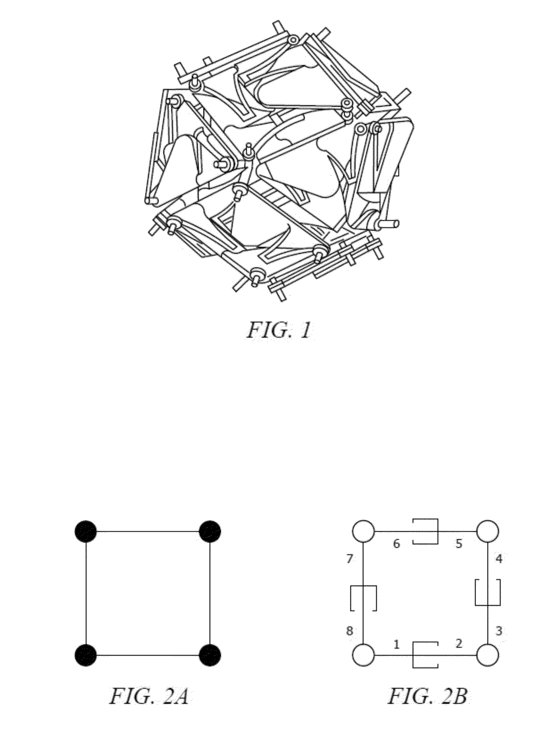
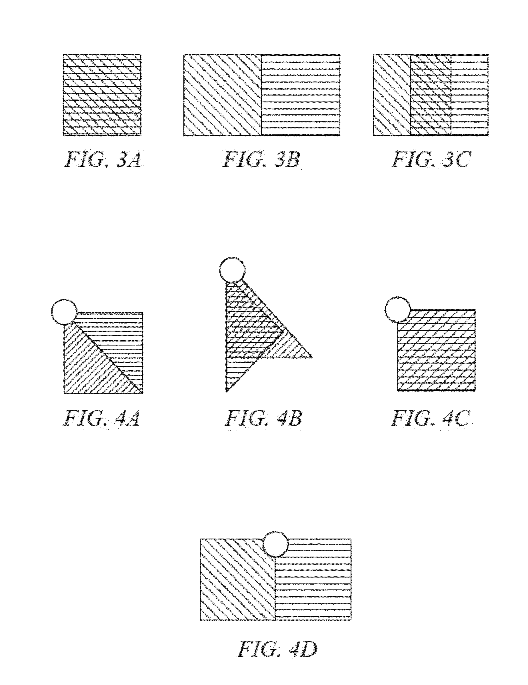
[0140]Applying these design rules, a square unit cell is chosen, and an application allows each of the four sides and four corners to be able to expand and contract. The minimum number of side members for which this can be achieved is eight (8). Each side of the square unit cell is associated with two side members, and each corner is associated with two side members. The two-thirds rule is used to select the length of the side member and the angle of the member attached at the node, as depicted in FIG. 4.

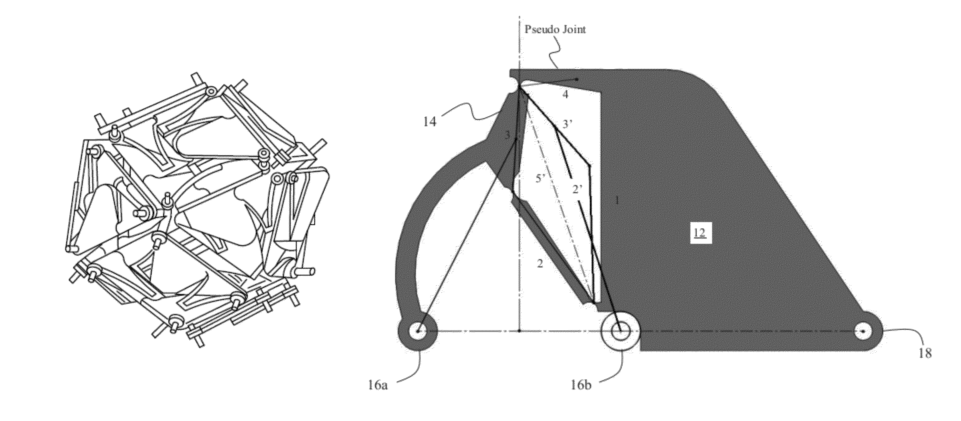
[0141]A compliant mechanism, depicted in FIG. 6A, also referred to as a side member, includes a compliant flexure 14 and a shield or plate segment 12 that functions as a link and slider. It can be seen that the rigid area-covering portion (i.e., plate segment) 12 constitutes two-thirds of the entire length of the side member. A one-third movement is possible in compression and expansion before gaps form. In addition, the angle at the node is two-thirds of a right angle. This allows ...

example 2

[0146]Eight side-members are assembled to form the deformable square unit cell depicted in FIG. 7A. FIG. 7B shows the unit cell in a stable sheared position. FIG. 7C shows the unit cell in a stable expanded (or tensed) position. FIG. 7D shows the unit cell a stable compressed position. The amount of deflection that the compliant mechanism can achieve is dependent on the mechanism's geometry and the material properties.

[0147]Depending upon the application, adjacent unit cells are designed to limit motion by sharing nodes, or to increase mobility by having separate sets of nodes that may translate with respect to each other. By leveraging the side members, the side members can be stabilized in one position, then sheared, expanded or compressed, and stabilized in the second position.

example 3

[0148]Large-scale geometric effects can be achieved by attaching dissimilar unit cells to each other in ways that put a first cell in tension (i.e., expansion) and a contiguous second cell in compression. For example, a conical surface is created by attaching a smaller compliant ring to a larger one as depicted in FIGS. 8A and 8B. The ability to mate unit cells of dissimilar size enables a discrete set of unit cell sizes to provide the adequate geometric flexibility to build a wide variety of surfaces with varying predetermined shapes of stability.

[0149]As depicted in FIGS. 8A and 8B, shape changes can be induced by joining unit cells of dissimilar size. Surfaces are developable if they can be formed by bending, but not stretching or compressing any part of a flat sheet. Multistable shape-shifting surfaces with flexible boundaries between unit cells can be assembled to form developable surfaces such as the one depicted in FIGS. 8A and 8B.

[0150]It is contemplated that the unit cells ...


PUM


Abstract

Multistable shape-shifting surfaces that retain their effectiveness as physical barriers while undergoing changes in shape and that can remain stable in the various shapes. The shape changes include any motion that makes the surface more effective at performing its function, such as expansion, shrinkage, twisting, encircling, wiggling, swallowing or constricting. The shape-shifting surfaces include tiled arrays of polygonal cells, each cell including specifically-designed compliant flexures attached to specifically-shaped overlapping thin plates or shells. The surfaces remain stable by leveraging them during deformation to an extent that they cannot spontaneously return to the unstressed shape. Applications for such surfaces include micro-scale cellular engineering and macro-scale biomedical applications, recreational uses, national security, and environmental protection.

Description

CROSS-REFERENCE TO RELATED APPLICATIONS[0001]This application is a continuation-in-part of and claims priority to currently U.S. patent application Ser. No. 13 / 302,606 entitled “Shape-Shifting Surfaces,” filed Nov. 22, 2011, which is a continuation of and claims priority to International Application Serial No. PCT / US2011 / 044370 entitled “Shape-Shifting Surfaces,” filed Jul. 18, 2011, which claims priority to U.S. Provisional Application No. 61 / 365,164, entitled “Design for Integrity in Shape-Shifting Surfaces”, filed Jul. 16, 2010, the contents of which are all hereby incorporated by reference into this disclosure. This application also claims priority to, and is a non-provisional of U.S. Provisional Application No. 61 / 537,372, entitled “Multistable Shape-Shifting Surfaces”, filed on Sep. 21, 2011 by the same inventors, the contents of which are also hereby incorporated by reference into this disclosure.FEDERALLY SPONSORED RESEARCH OR DEVELOPMENT[0002]This invention was made with Go...

Claims


Application Information

Patent Timeline
Patent Type & Authority Patents(United States)
IPC IPC(8): E04H12/18E04H9/00E04H14/00E04H9/02
CPCB25J9/08
Inventor LUSK, CRAIG PERRYMONTALBANO, PAUL JOSEPH
Owner UNIV OF SOUTH FLORIDA
Why Eureka
Try Eureka