System and method for integrated high frequency oscillatory ventilation

a high frequency oscillatory and ventilation system technology, applied in the field of clinical workflow, can solve the problems of reducing cardiac output, affecting ventilation efficiency, and affecting ventilation efficiency,

Active Publication Date: 2013-03-26
GENERAL ELECTRIC CO
View PDF17 Cites 10 Cited by
  • Summary
  • Abstract
  • Description
  • Claims
  • Application Information

AI Technical Summary

Benefits of technology

[0011]In accordance with further aspects of the present technique, a method for providing high frequency ventilation via use of a high frequency ventilation module, where the high frequency ventilation module is configured to be operationally coupled to a ventilation system, and where the high frequency ventilation module is configured to aid the ventilation system in performing high frequency ventilation is presented. The method includes creating a vacuum effect at an outlet port of the ventilation system to aid in active exhalation of gas from a patient.

Problems solved by technology

However, the effects of this non-physiological approach to ventilation are numerous and can be detrimental.
Furthermore, in diseased lungs, positive pressure ventilation may not always provide adequate carbon dioxide (CO2) clearance or oxygen delivery and may even result in alveolar and / or lung damage due to ventilating at high airway pressures.
The other side effects of positive pressure ventilation may include decreased cardiac output, reduced venous return, decreased urine output, retention of fluids, risk of ventilator associated pneumonia, and risk of tracheal and lung damage if gases are not humidified.
However, use of the standalone HFOV ventilator has huge cost implications.
Moreover, a transition between normal ventilation via use of the ICU ventilator and HFOV via the HFOV ventilator may unfortunately result in loss of pressure in the lungs of the patient, thereby causing discomfort to the patient.
Moreover, there are equipment, time, and training issues associated with having the HFOV function separate from the ICU ventilator.

Method used


Image

  • System and method for integrated high frequency oscillatory ventilation
  • System and method for integrated high frequency oscillatory ventilation
  • System and method for integrated high frequency oscillatory ventilation

Examples


Embodiment Construction

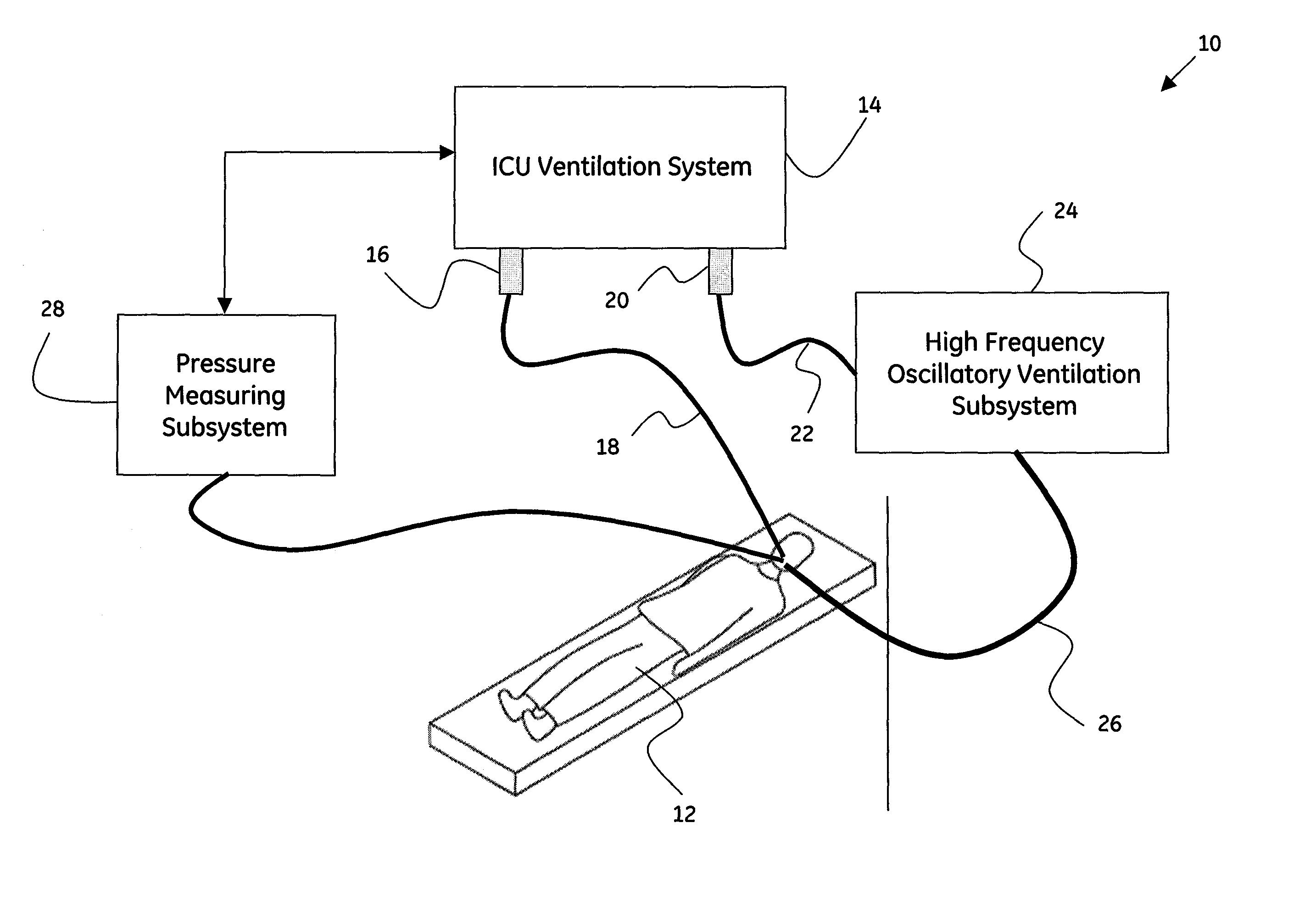
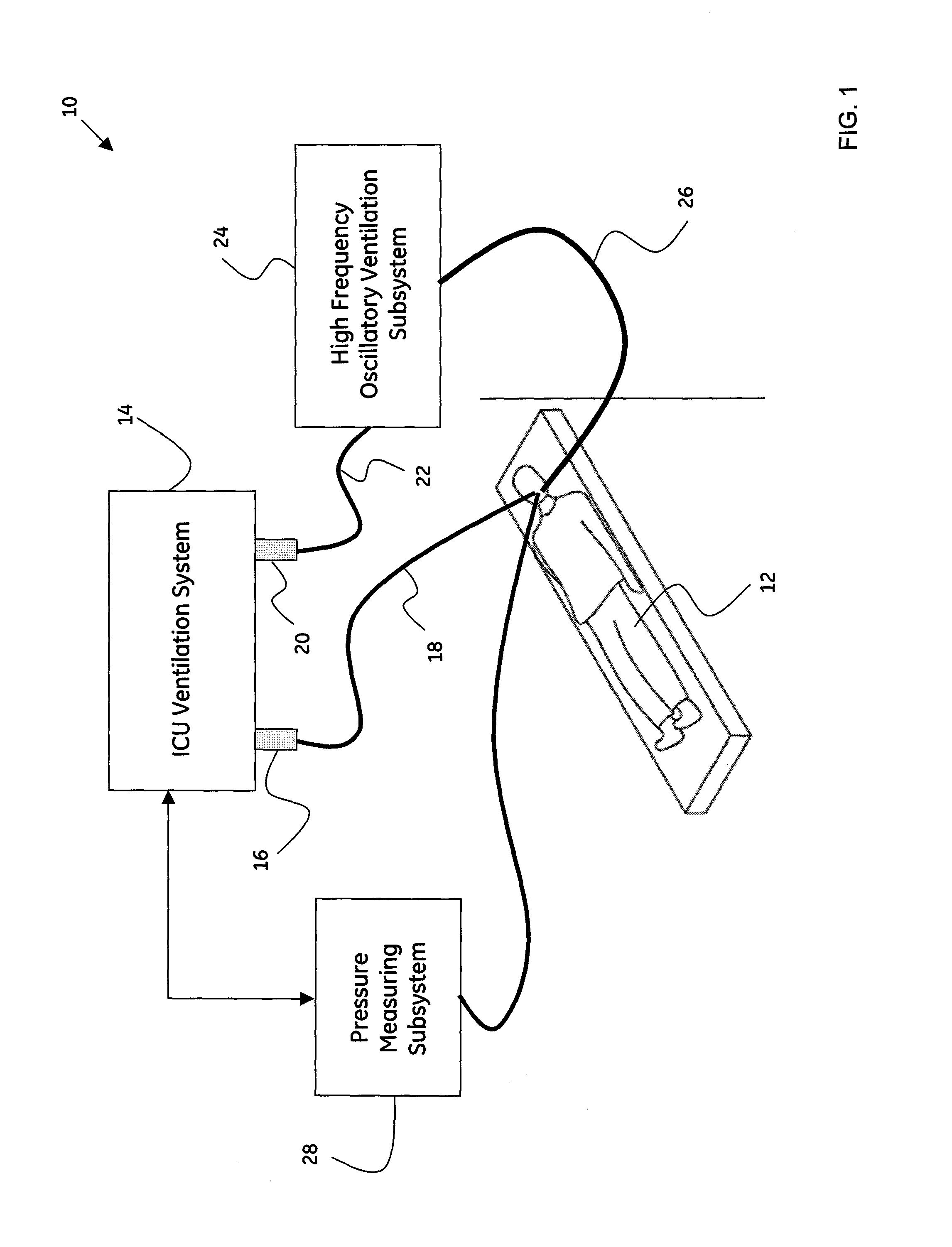
[0016]FIG. 1 is a block diagram of an exemplary integrated high frequency oscillatory ventilation (HFOV) system 10, in accordance with aspects of the present technique. More particularly, the system 10 may be configured to aid in providing integrated ventilation to a patient 12. In other words, the exemplary integrated HFOV system 10 may be configured to aid a traditional ICU ventilator in performing HFOV, thereby enhancing clinical workflow by providing seamless transition between normal ICU ventilation and HFOV, and preventing loss of circuit pressure during the transition and minimizing discomfort to the patient 12.

[0017]As previously noted, once a patient, such as the patient 12, has been identified as needing artificial ventilation, the patient 12 may be operationally coupled to a ventilation system 14. In a presently contemplated configuration, the ventilation system 14 may include a traditional ICU ventilation system. As will be appreciated, the ICU ventilation system 14 is a...


PUM


Abstract

An integrated ventilation system is presented. The integrated ventilation system includes a high frequency ventilation module configured to be operationally coupled to a ventilation system, where the high frequency ventilation module is configured to aid the ventilation system in performing high frequency ventilation. A method for providing high frequency ventilation via use of a high frequency ventilation module, where the high frequency ventilation module is configured to be operationally coupled to a ventilation system, and where the high frequency ventilation module is configured to aid the ventilation system in performing high frequency ventilation, is presented. The method includes creating a vacuum effect at an outlet port of the ventilation system to aid in active exhalation of gas from a patient.

Description

BACKGROUND[0001]This disclosure relates generally to clinical workflow, and more particularly to a design of a device configured to aid in enhancing clinical workflow.[0002]In a caregiving facility, such as a hospital, and more particularly, in an Intensive Care Unit (ICU), it may be desirable to provide artificial ventilation to one or more patients. As will be appreciated, patients in the ICU that have been identified as needing artificial ventilation are typically intubated and ventilated in order to treat and manage respiratory failures, such as asthma, pneumonia, pulmonary edema, pulmonary embolism, chronic bronchitis, post-operative hypoxemia, chest injuries and chronic lung disease. Along with patients suffering from respiratory failure, certain patients may need ventilatory support for other medical reasons. By way of example, post-operative ICU patients and certain maxillofacial surgical patients may also require a period of post operative care in the ICU, during which time...

Claims


Application Information

Patent Timeline
Patent Type & Authority Patents(United States)
IPC IPC(8): A61M16/00
CPCA61M16/0096A61M16/0051A61M2016/0027A61M16/022
Inventor LEVI, ANDREW PHILLIPBRAATZ, ROBERT EDWIN
Owner GENERAL ELECTRIC CO
Why Eureka
Try Eureka