Hand tool frame

a hand tool and frame technology, applied in the field of hand tool frames, can solve the problems of limiting the practicability of the conventional hand tool frame, and the inability to fit hand tools of different sizes

Active Publication Date: 2013-03-26
KAO JUI CHIEN
View PDF33 Cites 44 Cited by
  • Summary
  • Abstract
  • Description
  • Claims
  • Application Information

AI Technical Summary

Benefits of technology

[0008]The main objective of the present invention is to provide a hand tool frame that can be used to hold different sizes of hand tools conveniently.

Problems solved by technology

The inserting holes of the clamping panels of the conventional hand tool frame only can be used to hold the hand tools of specific sizes and cannot be fit with hand tools of different sizes.
Then, the user may need to buy multiple conventional hand tool frames of multiple different sizes to hold or store hand tools and this is inconvenient in use and will limit the practicability of the conventional hand tool frame.

Method used


Image

  • Hand tool frame
  • Hand tool frame
  • Hand tool frame

Examples


first embodiment

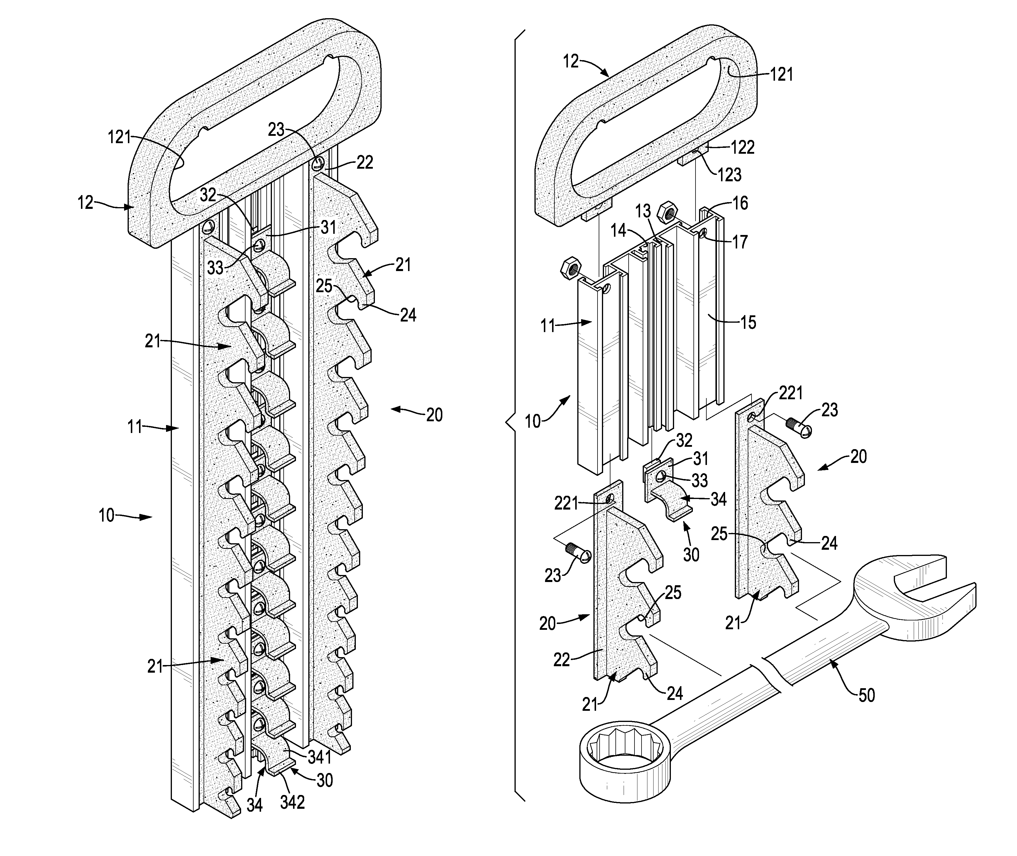
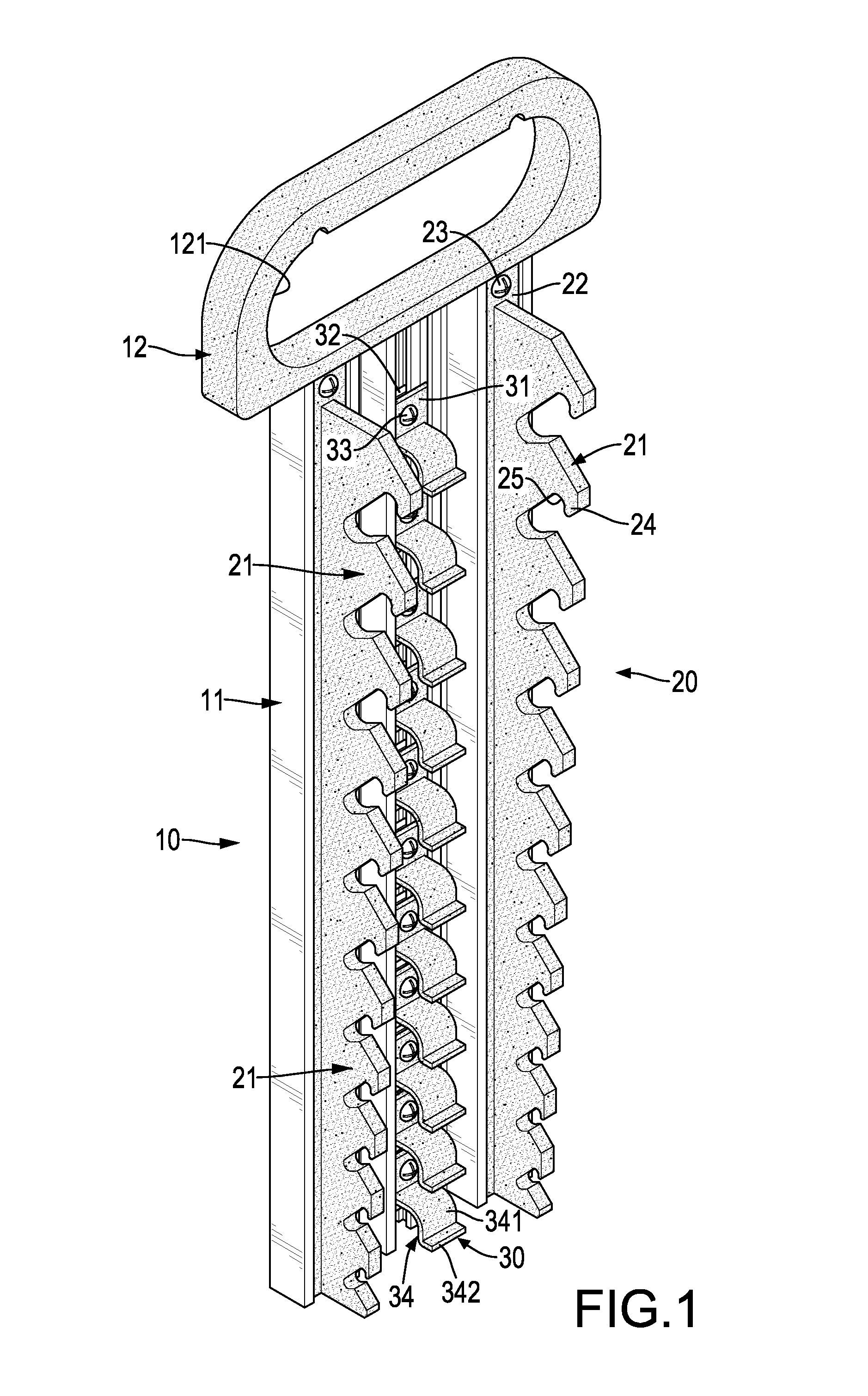
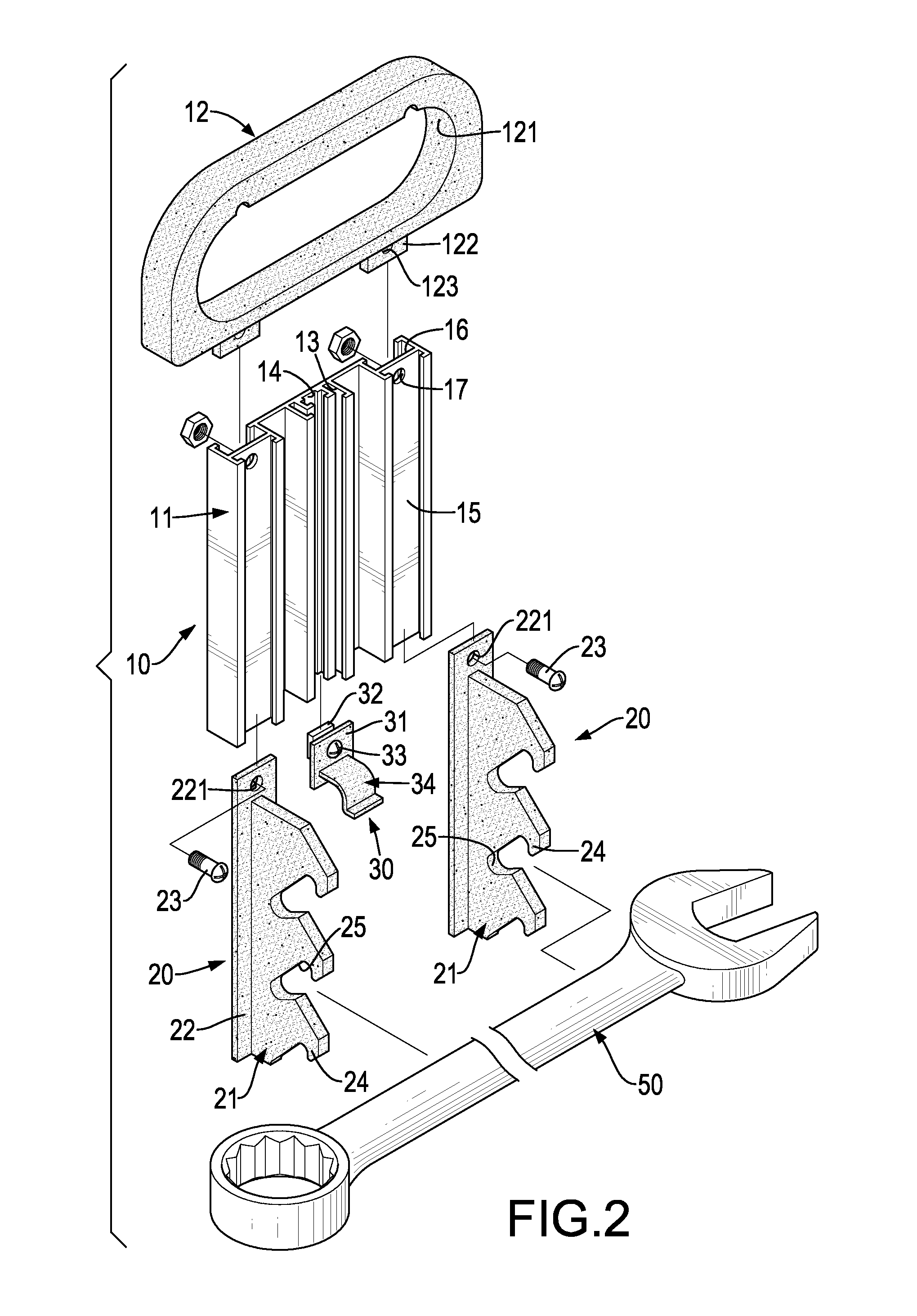
[0024]The baseboard 10, 10′ has a body 11, 11′ and a hanging panel 12, 12′. The body 11, 11′ is rectangular and has a front side, a rear side, a top and a bottom. With reference to FIGS. 2 and 3, the body 11 of the hand tool frame further has an outer rack 13, an inner rack 14, two front mounting recesses 15, two rear mounting recesses 16 and two passing holes 17. The outer rack 13 is formed on the front side of the body 11 from the top to the bottom of the body 11 and has a front side and an opening. The opening of the outer rack 13 is formed through the front side of the outer rack 13 and has a width (A) as shown in FIG. 6.

second embodiment

[0025]The inner rack 14 is formed on the front side of the body 11 from the top to the bottom of the body 11, is located in the outer rack 13 and has a front side and an opening. The opening of the inner rack 14 is formed through the front side of the inner rack 14 and has a width (B) as shown in FIG. 6. The front mounting recesses 15 are formed in the front side of the body 11 beside the outer rack 13 and parallel the outer rack 13. The rear mounting recesses 16 are formed in the rear side of the body 11 corresponding to the front mounting recesses 15. The passing holes 17 are formed through the sides of the body 11 near the top of the body 11 and respectively communicate with the front mounting recesses 15 and the rear mounting recesses 16. With reference to FIG. 11, the body 11′ of the hand tool frame has multiple open holes 18′ formed through the sides of the body 11′ at intervals.

[0026]The hanging panel 12, 12′ is connected to the top of the body 11, 11′ and has a hanging hole ...


PUM


Abstract

A hand tool frame has a baseboard, two clamping elements and multiple positioning elements. The baseboard has a body and a hanging panel. The hanging panel is connected to the top of the body and has a hanging hole. The clamping elements are mounted on the baseboard and each clamping element has a clamping panel. Each clamping panel has multiple clamping claws and multiple inserting holes. The positioning elements are mounted on the baseboard at intervals between the clamping elements with the same sizes and each positioning element has an elastic arm. The elastic arm is formed on and protrudes from the body and has a curved segment and a limiting segment. The limiting segment is formed on and protrudes from the curved segment to abut against a hand tool.

Description

BACKGROUND OF THE INVENTION[0001]1. Field of the Invention[0002]The present invention relates to a tool frame, and more particularly to a hand tool frame that can be used to hold hand tools of different sizes conveniently.[0003]2. Description of the Prior Art[0004]A conventional hand tool frame is used to hold or store hand tools such as wrenches and has a baseboard, two clamping panels and multiple pressing bars. The baseboard has a top, a front side and a hanging hole. The hanging hole is formed through the baseboard near the top of the baseboard. The clamping panels are formed on and protrude from the front side of the baseboard at an interval below the hanging hole and parallel each other. Each clamping panel has a front side, multiple clamping claws and multiple inserting holes. The clamping claws are formed in the front side of the clamping panel at intervals and have different sizes. The inserting holes are formed in the front side of the clamping panel between the clamping c...

Claims


Application Information

Patent Timeline
Patent Type & Authority Patents(United States)
IPC IPC(8): A47F7/00B65D85/28
CPCA47F7/00B25H3/04
Inventor KAO, JUI-CHIEN
Owner KAO JUI CHIEN
Why Eureka
Try Eureka