Sliding apparatus and sliding structure
a technology which is applied in the field of sliding apparatus and sliding structure, can solve the problems of preventing assembly workability, complicated work in the manufacture, and inability to address a variety of requirements and applications, so as to improve workability and productivity, the effect of increasing the number of parts
- Summary
- Abstract
- Description
- Claims
- Application Information
AI Technical Summary
Benefits of technology
Problems solved by technology
Method used
Image
Examples
second embodiment
[0117]Next is a description of the present invention.
[0118]FIG. 10 is an elevation view showing an extended state of a slide rail as a sliding apparatus of a second embodiment of the present invention. FIGS. 11A to 11F are diagrams for explaining a movement of a retaining pin when the slide rail of the second embodiment of the present invention is shifted from an extended state to a retracted state. FIGS. 12A to 12F are diagrams for explaining a restoration procedure when a retaining pin of the slide rail of the second embodiment of the present invention is unintentionally released from a standby position. FIG. 13 is an elevation view showing a modification of the slide rail as the sliding apparatus of the second embodiment of the present invention.
first embodiment
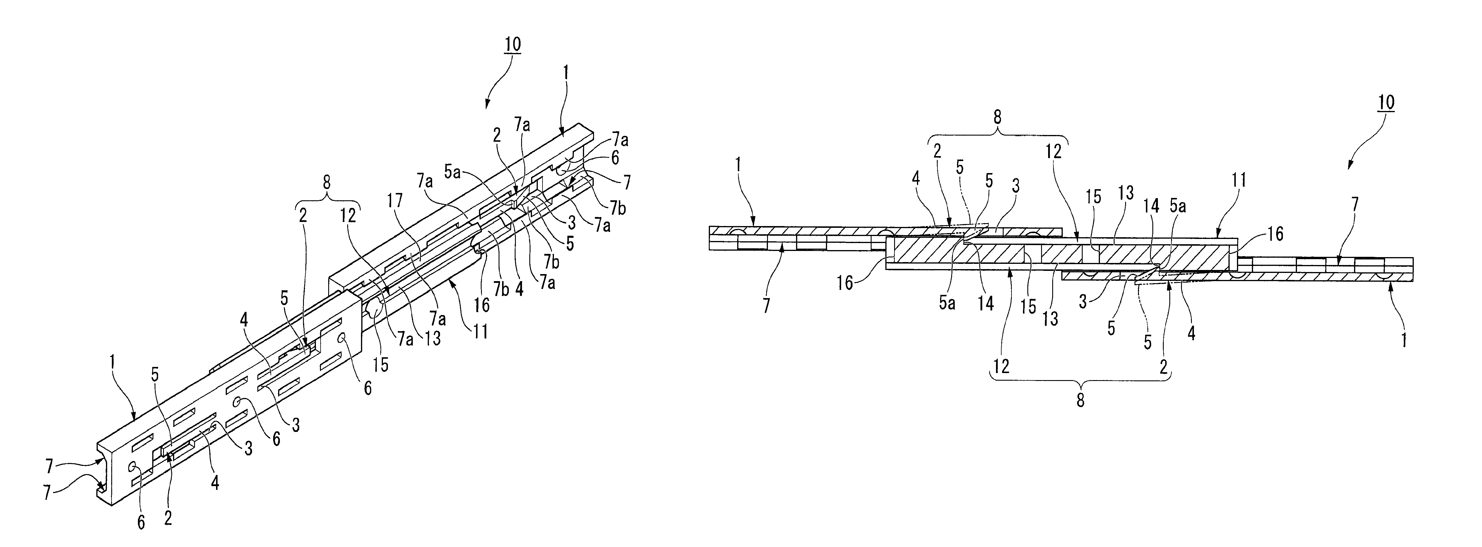
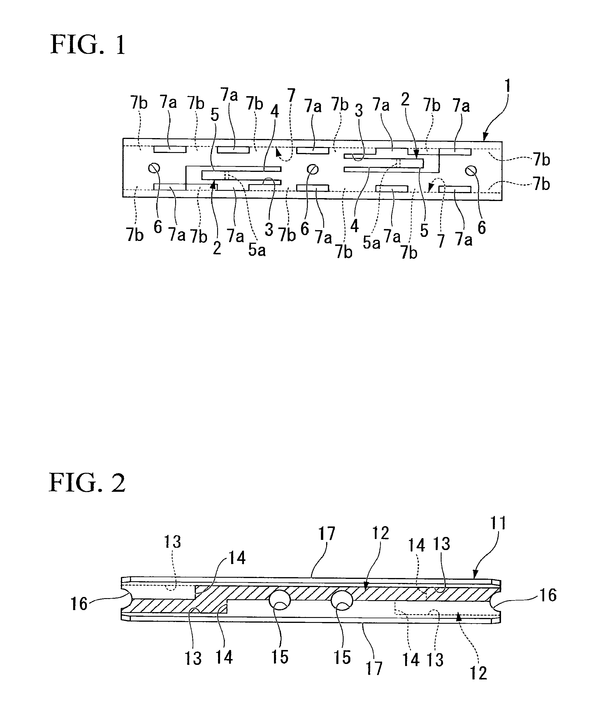
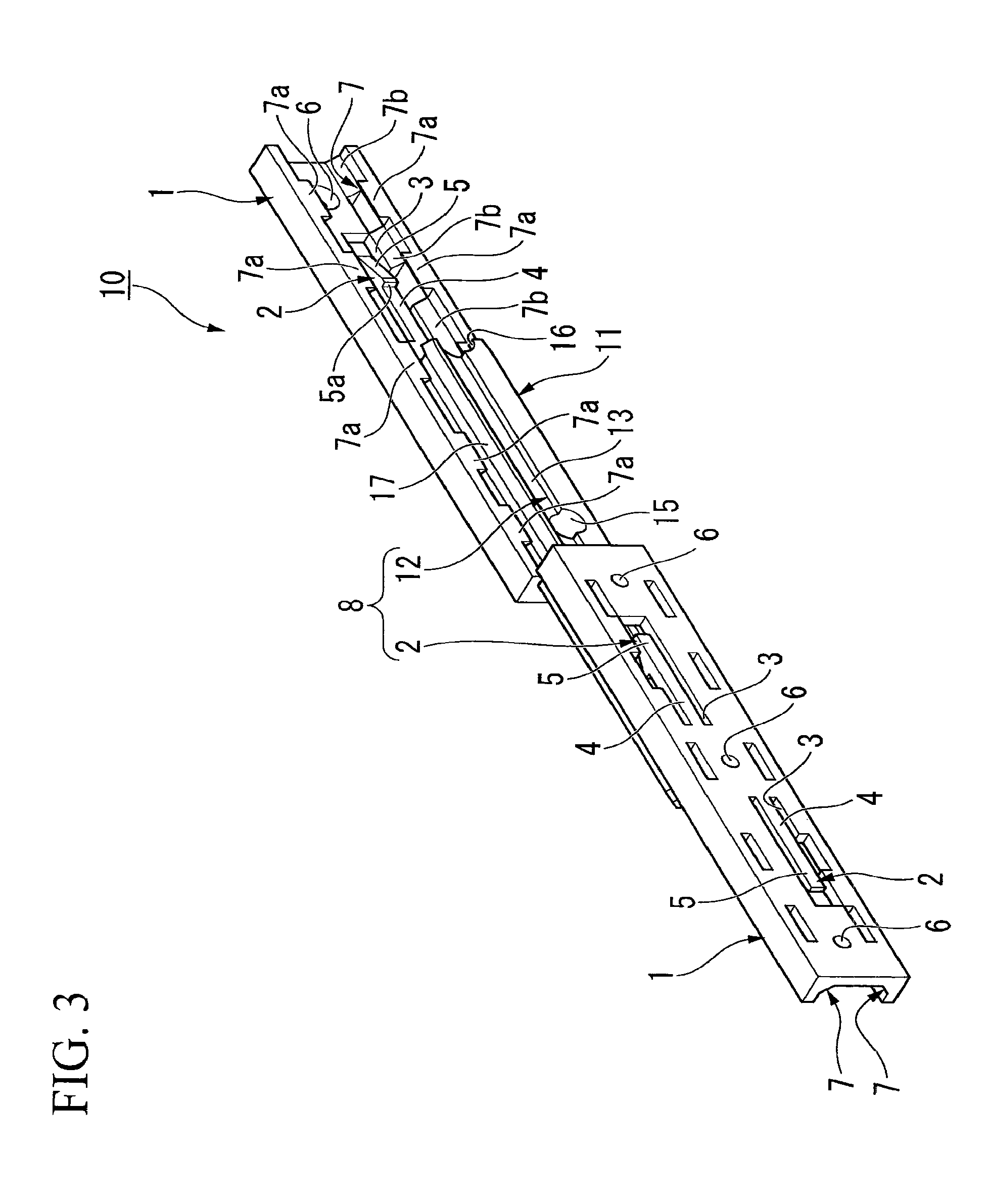
[0119]Note that like members to those of the slide rails 10, 20 of the aforementioned first embodiment are designated with like reference numerals and are not repetitiously explained.
[0120]As shown in FIG. 10, a slide rail 30 of the present invention is formed of: two first rails 1 (1a, 1b); and a second rail 11 that is arranged so as to be caught between the first rails 1a, 1b. Furthermore, the slide rail 30 includes a terminal biasing device 31 that moves the two first rails 1a, 1b and the second rail 11 relatively so that the two first rails 1a, 1b and the second rail 11 are brought closer to each other. The terminal biasing device 31 also acts, for biasing the relative movement, at a position slightly closer to a terminal position of stroke in a retracted state where the outer dimension of the slide rail 30 in the longitudinal direction is maximally retracted.
[0121]Of the two first rails 1a, 1b of the slide rail 30, the first rail 1a includes a cam member 32 on the lower end por...
third embodiment
[0159]Next is a description of the present invention.
[0160]FIG. 14 is a schematic perspective view showing a drawer body provided with a sliding structure of a third embodiment according to the present invention. Note that like members to those of the aforementioned first and second embodiments are designated with like reference numerals and are not repetitiously explained.
[0161]As shown in FIG. 14, the drawer body 60 is made of, for example, a resin or the like. The drawer body 60 includes: a box-shaped casing 61 (base body) as a main unit portion thereof, and a drawer 62 (movable body) that moves relatively with respect to the casing 61 and is extractable / retractable from / into the casing 61. On both of the side surface portions of the drawer 62, two second rails 11a (11) are provided that extend in a direction in which the drawer 62 reciprocally moves with respect to the casing 61, the second rails 11a being formed integrally with the drawer 62.
[0162]Furthermore, on both of the si...
PUM
 Abstract
Description
Claims
Application Information
 - R&D
- Intellectual Property
- Life Sciences
- Materials
- Tech Scout
- Unparalleled Data Quality
- Higher Quality Content
- 60% Fewer Hallucinations
Browse by: Latest US Patents, China's latest patents, Technical Efficacy Thesaurus, Application Domain, Technology Topic, Popular Technical Reports.
© 2025 PatSnap. All rights reserved.Legal|Privacy policy|Modern Slavery Act Transparency Statement|Sitemap|About US| Contact US: help@patsnap.com


