Detection of respiratory system lesions

a technology for respiratory systems and lesions, applied in the field of lesions detection of respiratory systems, can solve the problems of ineffective early screening programmes, inefficient use of resources, and inability to meet demand

Active Publication Date: 2013-03-26
ANAXSYS TECH LTD
View PDF15 Cites 10 Cited by
  • Summary
  • Abstract
  • Description
  • Claims
  • Application Information

AI Technical Summary

Benefits of technology

[0010]For this purpose, the individual will exhale breath whereby it impinges on the sensing element of a sensor for sensing water vapour in a gas stream. As indicated above this may be a known form of respiratory sensor as described for example in WO 2008 / 009980 having a conduit through which the subject can both inhale air drawn in through an inlet and exhale air whereby it is channelled to the sensing element. However, it has been found preferable for breath to be delivered to the humidity sensing element as non-laminar flow equating with a Reynolds number of greater then 2000. This may be achieved by exhalation into a narrow conduit which directs exhaled air to the sensing element, e.g. a conduit selected with bore between 10 and 20 mm, and preferably in the range of 15 to 18 mm, and using a breathing technique to give turbulent flow (for example faster breathing than normal). In this way, humidity changes of interest which develop in the respiratory system are less liable to be lost or reduced.

Problems solved by technology

In part this is because lung cancer tends to present late and there is no effective early screening programme.
If smokers were to be referred for imaging every time a new respiratory symptom appears, as some advise, then the healthcare infrastructure would be ill-equipped to cope with demand and this could be seen as an inefficient use of resources.
The lack of availability of suitable screening tools to aid decision making on referral for confirmatory lung cancer diagnosis and treatment is thus a constant cause of frustration for oncologists.
CT scanning presents difficulty in picking up sufficient tumours to justify screening as routine; there is high financial cost and limitations on CT facilities.
In addition, the risk of radiation-induced cancers (estimated at 1 fatality per 1300 patients scanned) makes this an unsuitable large scale tool.
However, even with highly sensitive machines, no true specificity has been demonstrated and again the high cost of such technology is a problem.

Method used


Image

  • Detection of respiratory system lesions
  • Detection of respiratory system lesions
  • Detection of respiratory system lesions

Examples


example 1

[0061]Humidity profiles were obtained in trial conducted on subjects using an electrochemical sensor prepared as follows:

Sensor Construction

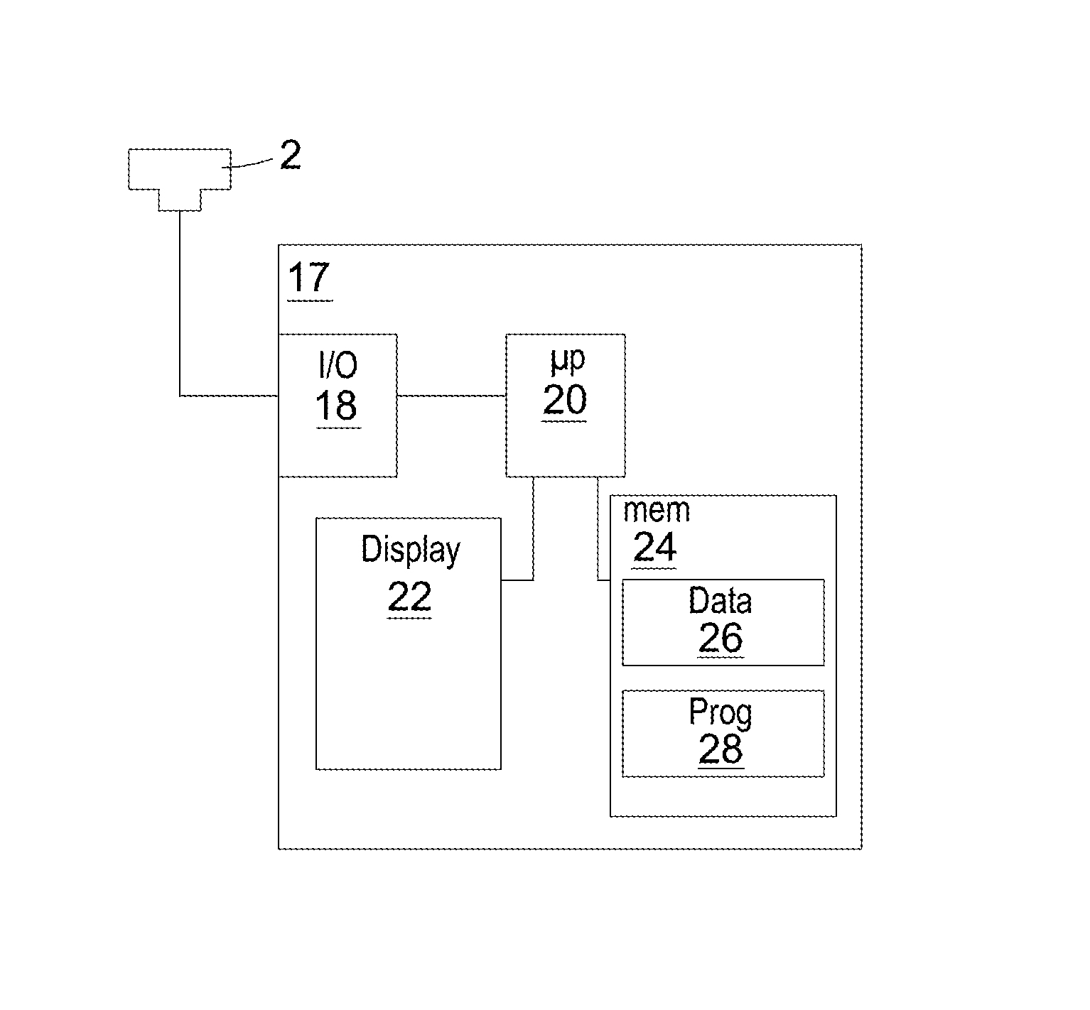
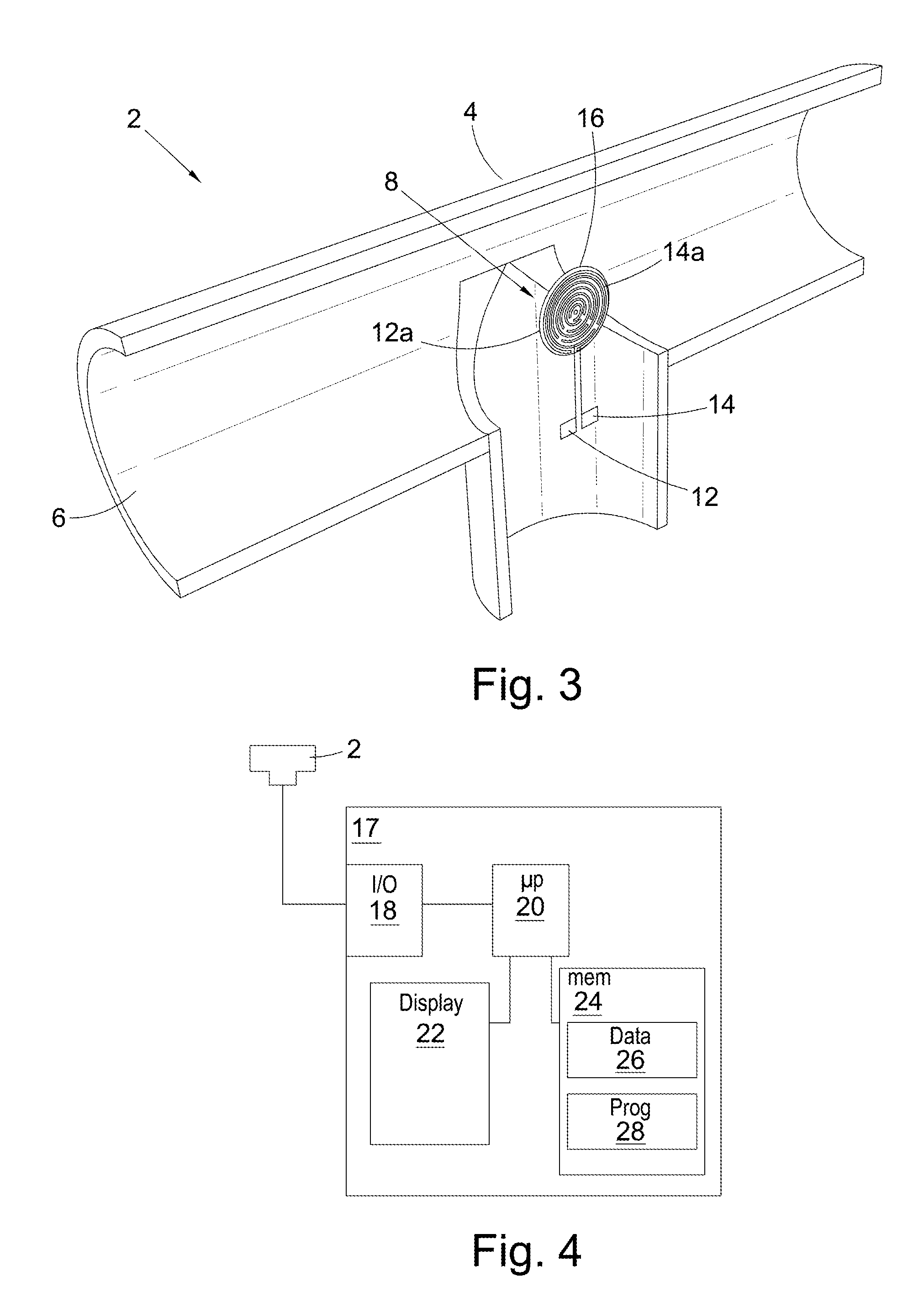
[0062]A sensor assembly having the general configuration shown in FIG. 3 was prepared. The electrodes were coated with an ion exchange layer comprising a commercially available sulphonated tetrafluoroethylene copolymer (Nafion®, ex Du Pont)

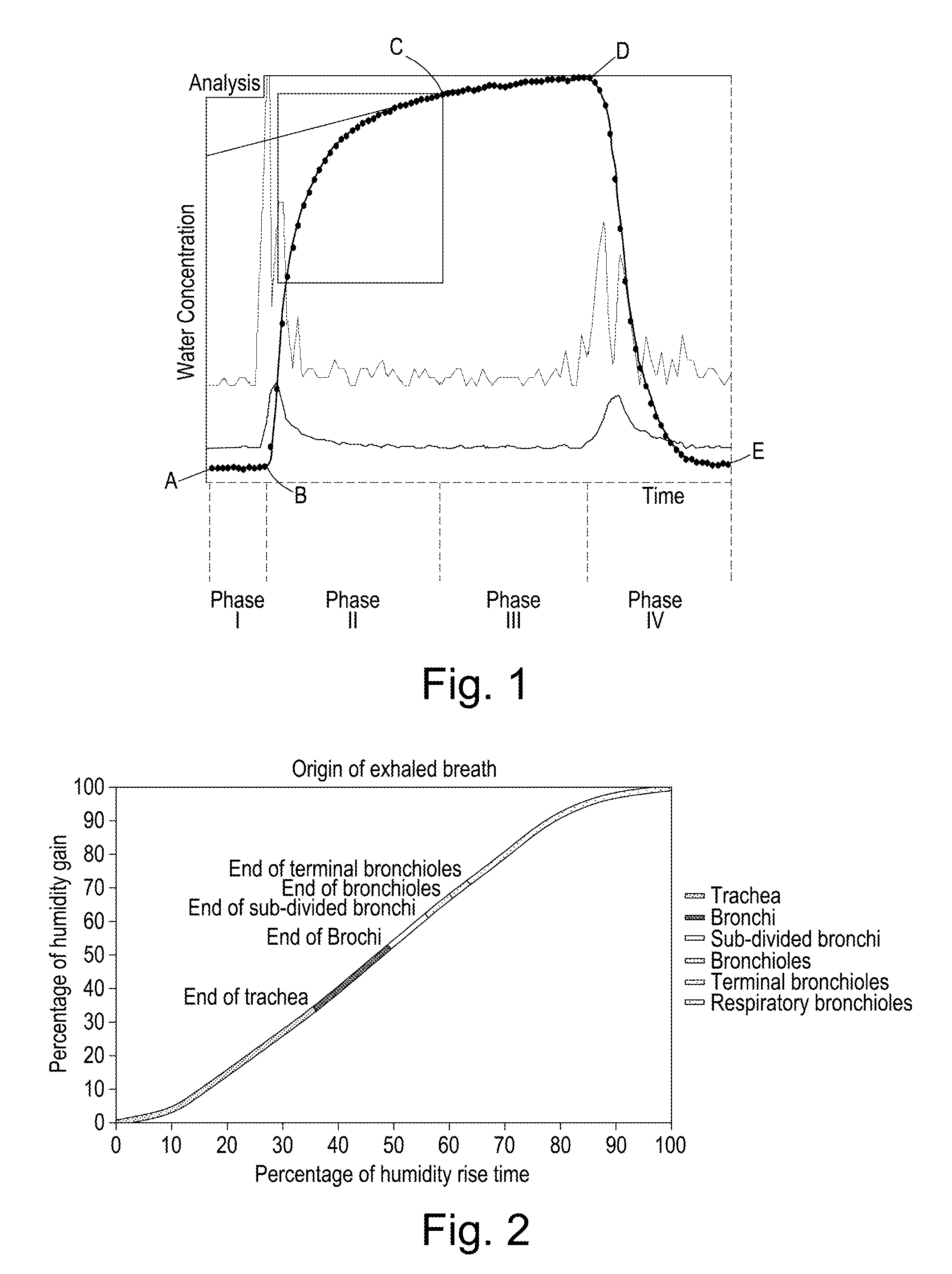
[0063]Using this type of sensor device to obtain humidity profiles of water vapour content versus time for exhaled breath a number of subjects were identified who gave profiles with an indent in the phase II initial upward curve portion. The health of these subjects was subsequently further investigated and the indents correlated with a lung lesion.

example 1a

[0064]A subject A known to be suffering from interstitial lung disease was caused to exhale into the sensor assembly. The change in the content of water vapour during the time of the exhalation was determined and the profile is shown in FIG. 7.

[0065]The profile follows the general pattern described above, that is having Phases I, II, III and IV bounded by points A, B, C, D and E, as described above and expected of a healthy subject. However, as can be seen from the figure, an irregularity can be identified in the profile in the region indicated as X, corresponding to the middle to later portion of Phase II of the profile. In particular, the profile indicates that the general increase in water vapour content over time during Phase II slowed at point Y. After point Y, the content of water vapour detected in the exhaled gas stream was less than expected. The expected increase in water vapour content, as determined by interpolation between the start and end points of Phase II, is shown ...

example 1b

[0067]Subject B, a male, 36 years of age, ex-smoker, was asked to exhale into the sensor assembly. The assembly determined the change in water vapour content over the time of exhalation. The profile thus generated is shown in FIG. 8.

[0068]As can be seen, by comparing the profile of FIG. 8 of Subject A with the profile of FIG. 1 of a healthy person, it can be noted that Phase II of the profile contains a deviation from the pattern expected of a healthy subject. In particular, it can be seen that the profile is not smooth and contains a discontinuity, such that the content of water vapour in the gas exhaled during the middle to later portion of Phase II was lower than expected. Subject A was subjected to further investigations.

[0069]Subject B complained of chest and back pains, was diagnosed as having dyspnea and a dry cough. Further examination of the subject revealed the right lung to be normal, but the left lung to be compressed at the upper lobe bronchus. A CT scan was conducted a...


PUM


Abstract

Humidity profiles of exhaled air of individuals obtained using a sensor to detect water vapor content or temperature versus time of exhalation may exhibit an irregularity indicative of a space-occupying respiratory system lesion. Detection of such irregularities provides an inexpensive and rapid means of pre-screening individuals for lung cancer diagnosis, and is applicable even to individuals with other respiratory disorders such as asthma and COPD.

Description

FIELD OF THE INVENTION[0001]The present invention relates to determining the presence of space-occupying lesions in the respiratory system of individuals, especially such lesions affecting the lungs or airways, relying on determination of irregularity in the humidity or temperature profile of exhaled breath. Such determination provides a simple, fast means of pre-selecting individuals for diagnosis of respiratory system lesions such as a lung tumour, even at a very early stage of development. While a sensor for this purpose may be a known form of electrochemical sensor as used for determination of respiratory function, e.g. assessing deterioration of respiratory function arising from asthma and / or chronic obstructive lung disease (COPD), also now disclosed are novel sensors for use in predicting the presence of respiratory system lesions as described further herein.BACKGROUND TO THE INVENTION[0002]The current 5-year survival rate for of lung cancer is 16% in developed countries. In ...

Claims


Application Information

Patent Timeline
Patent Type & Authority Patents(United States)
IPC IPC(8): A61B5/08
CPCA61B5/08A61B5/082A61B2562/029
Inventor WILLIAMS, DERYK JOHN PETERVARNEY, MARK SINCLAIRGARRETT, MICHAEL
Owner ANAXSYS TECH LTD
Why Eureka
Try Eureka