Implant for the treatment of lumbar spinal canal stenosis

a technology for lumbar spinal canals and implants, applied in the field of implants for treating lumbar spinal canal stenosis, can solve the problems of reducing the risk of post-operative complications and the risk of complications is considerabl

Inactive Publication Date: 2013-03-26
TIKOM
View PDF13 Cites 44 Cited by
  • Summary
  • Abstract
  • Description
  • Claims
  • Application Information

AI Technical Summary

Benefits of technology

[0006]It is therefore the object of the present invention to provide an implant for treating lumbar spinal canal stenosis which is as small and simple as possible, but which may in particular be inserted by way of unilateral intervention.

Problems solved by technology

Since, as already mentioned, the stenosis patients are often older people and they often also suffer from co-morbid conditions, the risk of complications is considerable.
However, one would not do this for safety reasons, since the element with the processes is screwed, and as a result one would operate on both sides of the spinal column for a secure control.
The smaller the implant and the smaller the operation, the lower the risk of post-operative complications.

Method used


Image

  • Implant for the treatment of lumbar spinal canal stenosis
  • Implant for the treatment of lumbar spinal canal stenosis
  • Implant for the treatment of lumbar spinal canal stenosis

Examples


Embodiment Construction

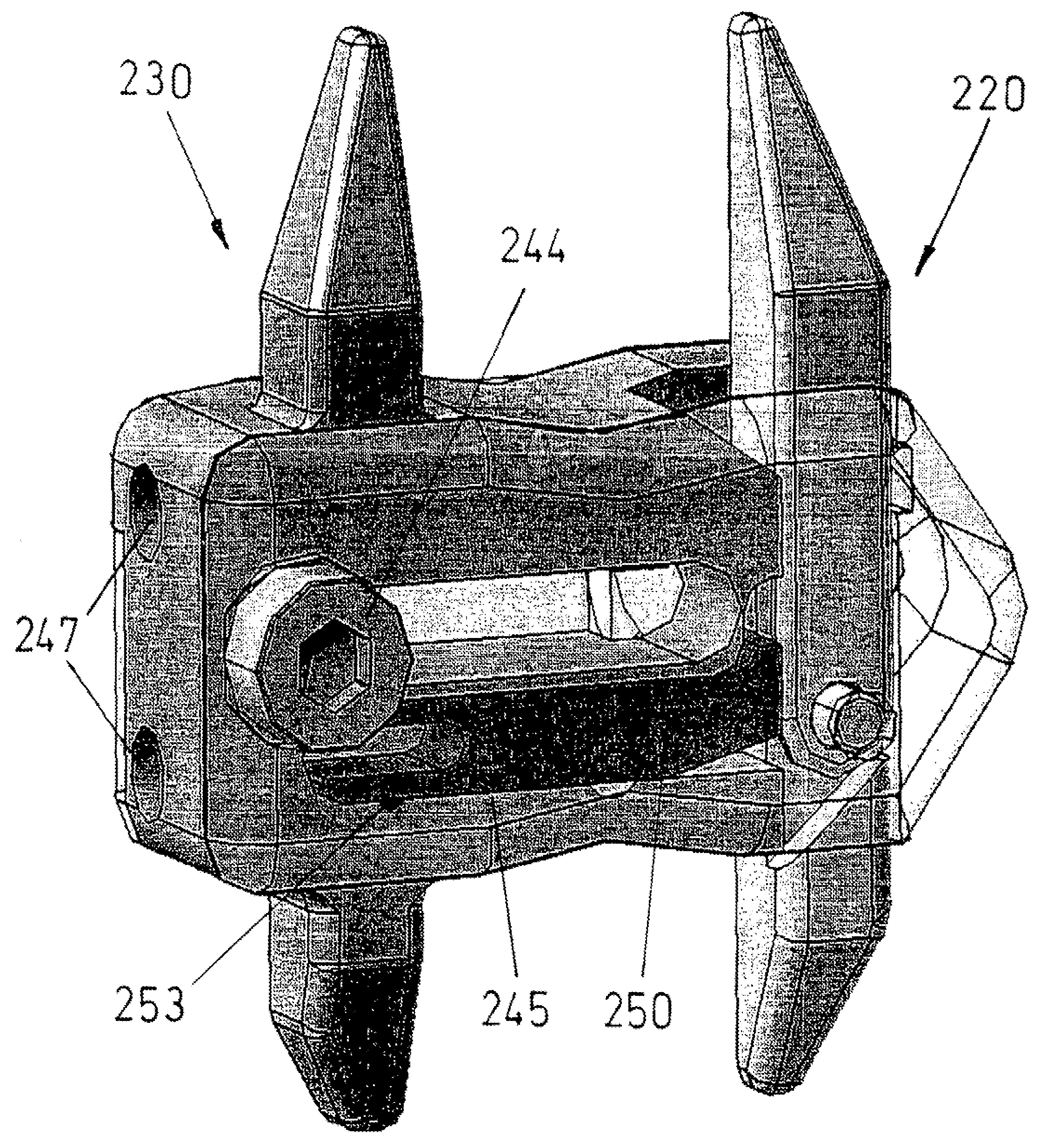
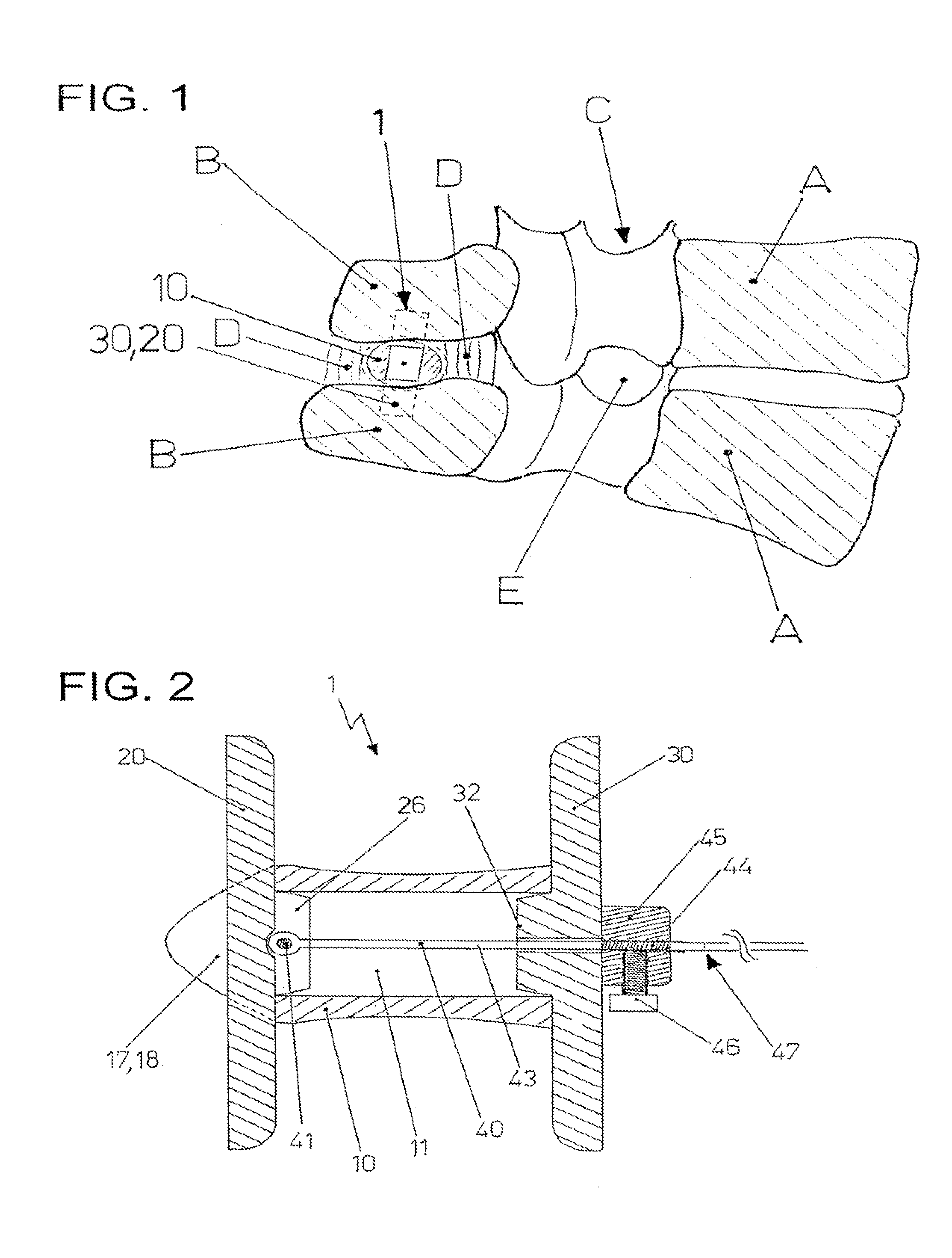
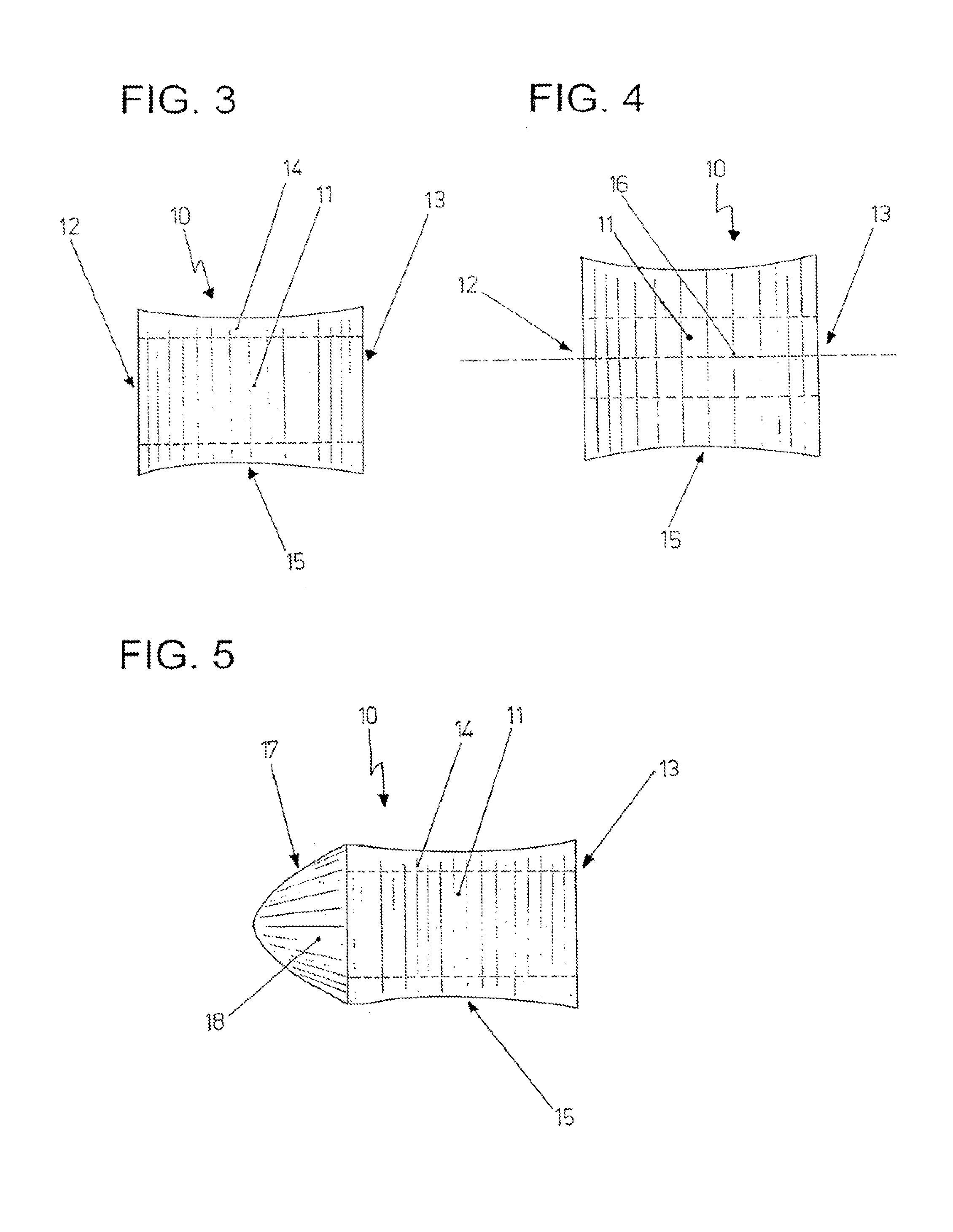
[0039]The situation with regard to a patient is shown in FIG. 1. Two adjacent vertebral bodies or vertebrae are shown at A. Their spinous processes are indicated at B. The spinal canal C runs between the vertebral bodies A and the spinous processes B. E represents the exit locations of the nerve roots. The interspinal ligament D runs between two adjacent spinous processes B. A spacer 10 crosses through this ligament, and in its position is secured against transversal displacement by a first retaining element 20 on the one side, and by a second retaining element 30 on the other side. This securement is however hardly effective since the spacer 10 is designed in a waisted manner and thus centers between the two spinous processes B.

[0040]Implants of this type are required when signs of the so-called Baastrup / kissing spine syndrome appear. The Baastrup syndrome indicates the contacting of two adjacent spinous processes. In this situation, the supraspinal ligament is forwardly curved tow...


PUM


Abstract

Disclosed is an implant for treating lumbar spinal canal stenosis, comprising a spacer that is proved with an elongate interior space into which an insert part can be inserted. A first retaining element is fixed in the spacer in the inserted state. Said first retaining part can be folded apart by inserting the insert part while a second rear retaining element that is molded onto the insert part simultaneously comes to rest on the vertebral processes, thus making it possible to insert the implant unilaterally while reducing the risk of having to undergo possible postoperative interventions.

Description

FIELD OF THE INVENTION[0001]The present invention relates to an implant for treating lumbar spinal canal stenosis, with a spacer which may be attached between spinous processes of two adjacent vertebral bodies.BACKGROUND OF THE INVENTION[0002]Spinal canal stenosis is to be understood as any form of narrowing of the spinal canal through which the spinal chord runs, whilst excluding inflammation, tumors and complete slipped disks. Most commonly, spinal canal stenosis takes place in the region of the lumbar spine, but it also occurs in the region of the thoracic spine and cervical spine. The most common cause of the acquired spinal canal stenosis is degenerative changes on the spinal column. Such degenerative changes of the bone-cartilage system occur more commonly with older patients. Therapeutically, one initially intervenes with anesthetic medication, such as non-steroid anti-rheumatics or by way of creating a lordosis correction by way of bandages or corsets. If this is inadequate,...

Claims


Application Information

Patent Timeline
Patent Type & Authority Patents(United States)
IPC IPC(8): A61B17/70
CPCA61B17/7065
Inventor DOLLINGER, HORST
Owner TIKOM
Why Eureka
Try Eureka