Methods and tooling assemblies for the manufacture of metallurgically-consolidated turbine engine components

a technology of turbine engine and tooling assembly, which is applied in the direction of manufacturing tools, turbines, and solventing apparatus, etc., can solve the problems of oxidation or other forms of chemical degradation, high mechanical stress, and high thermal and mechanical demands on gte components

Active Publication Date: 2013-04-02
HONEYWELL INT INC
View PDF39 Cites 41 Cited by
  • Summary
  • Abstract
  • Description
  • Claims
  • Application Information

AI Technical Summary

Problems solved by technology

However, as turbine inlet temperatures and rotational speeds increase, so too do the thermal and mechanical demands placed on the GTE components.
The turbine blades, in particular, are directly exposed to combustive gas flow at or near peak temperatures and are consequently heated to exceedingly high temperatures at which most alloys weaken or melt and become prone to oxidation or other forms of chemical degradation.
By comparison, the inner portion of the turbine (commonly referred to as the “turbine disk”) is largely shielded from direct exposure to combustive gas flow, but is subject to considerable mechanical stressors resulting from the centrifugal forces acting on the turbine rotor at high rotational speeds.
While enabling fabrication of the turbine blades and the rotor disk from disparate...

Method used


Image

  • Methods and tooling assemblies for the manufacture of metallurgically-consolidated turbine engine components
  • Methods and tooling assemblies for the manufacture of metallurgically-consolidated turbine engine components
  • Methods and tooling assemblies for the manufacture of metallurgically-consolidated turbine engine components

Examples


Embodiment Construction

[0022]The following Detailed Description is merely exemplary in nature and is not intended to limit the invention or the application and uses of the invention. Furthermore, there is no intention to be bound by any theory presented in the preceding Background or the following Detailed Description.

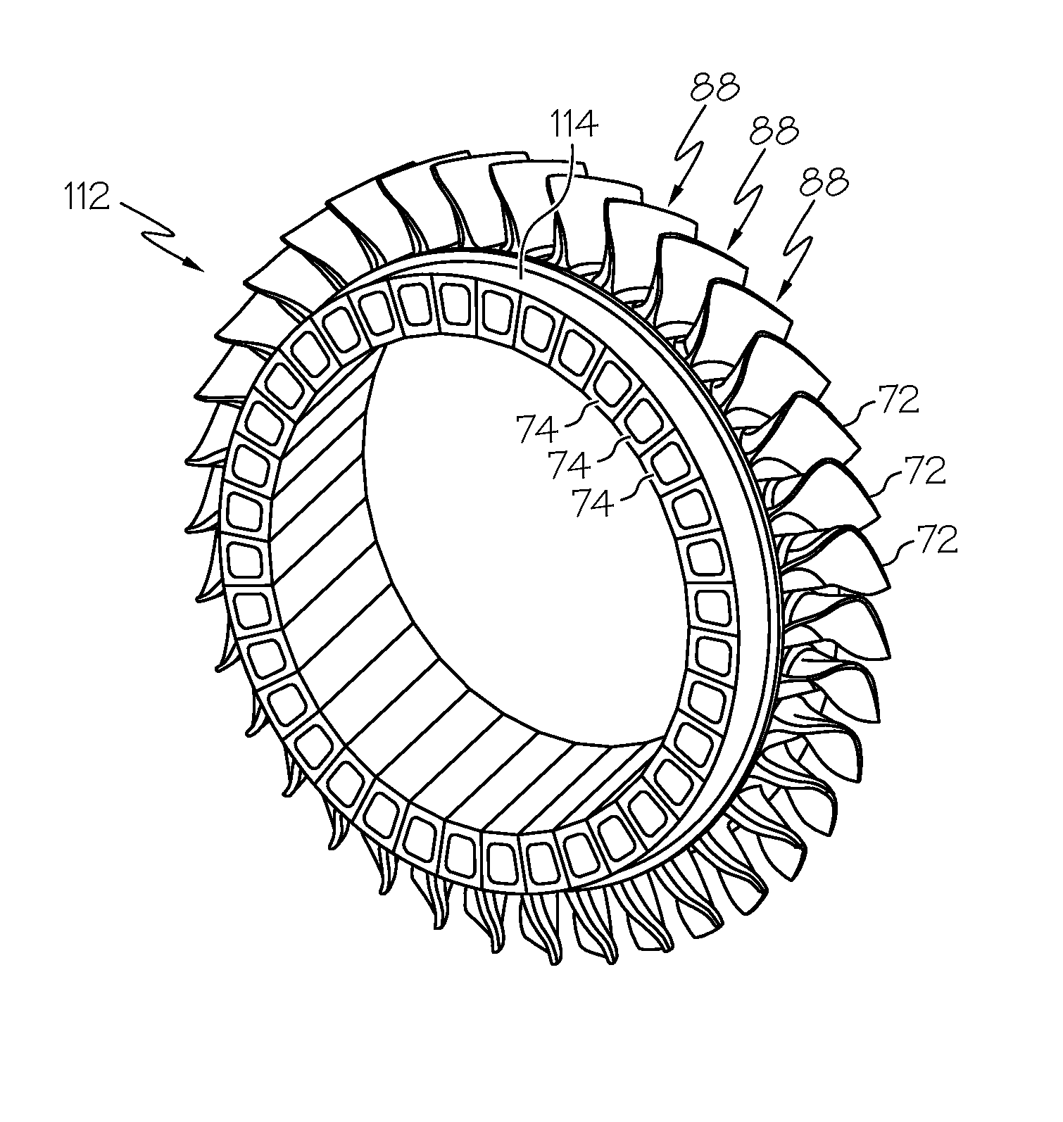
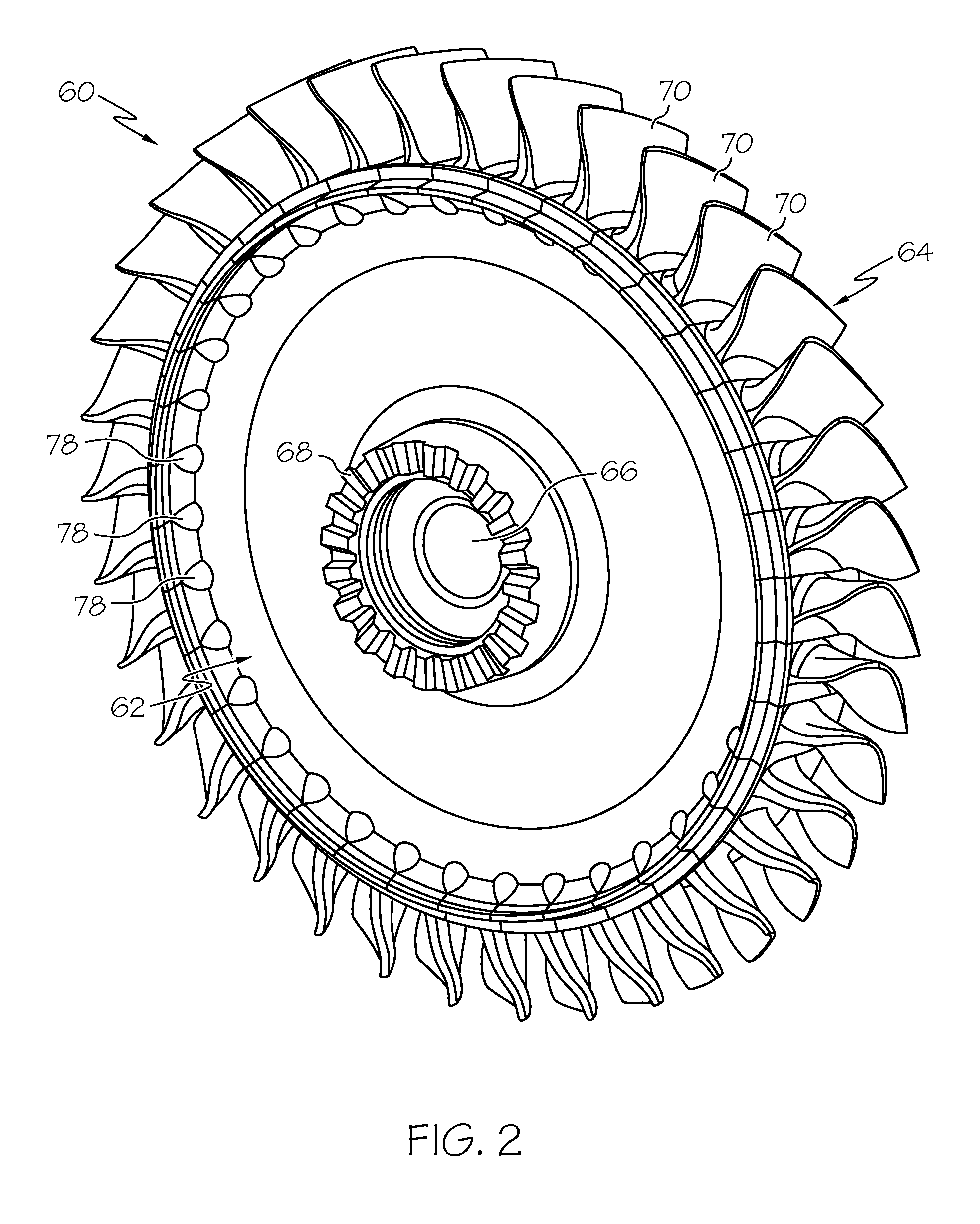
[0023]The following describes embodiments for manufacturing turbine engine components wherein a plurality of discrete, arched pieces are inter-bonded or arch-bonded utilizing a directed thermal growth bonding process to yield a metallurgically-consolidated, monolithic ring. Embodiments of the manufacturing process described herein are especially well-suited in the production of annular engine components including a number or circumferentially-spaced airfoils, such as turbine rotors, compressor rotors, and turbine nozzle rings. For example, when utilized to produce a turbine rotor, embodiments of the manufacturing process can be utilized to inter-bond a number of individually-fabricated blade...


PUM

PropertyMeasurementUnit
Temperatureaaaaaaaaaa
Thicknessaaaaaaaaaa
Melting pointaaaaaaaaaa

Abstract

Embodiments of a method for manufacturing a turbine engine component are provided, as are embodiments of a thermal growth constraint tool for the manufacture of turbine engine components. In one embodiment, the method includes the steps of obtaining a plurality of arched pieces, arranging the plurality of arched pieces in a ring formation, and bonding the plurality of arched pieces together to produce a monolithic ring by heating the ring formation to a predetermined bonding temperature while constraining the outward radial growth thereof.

Description

TECHNICAL FIELD[0001]The present invention relates generally to gas turbine engines and, more particularly, to methods and tooling assemblies utilized in the manufacture of turbine engine components including, but not limited to, turbine rotors, compressor rotors, and turbine nozzle rings.BACKGROUND[0002]Gas turbine engines (“GTE”) have been engineered extensively to improve efficiency, thrust-to-weight ratios, and other measures of engine performance. One of the most direct manners by which engine performance can be improved is through increases in the core rotational speeds and turbine inlet temperatures generated during engine operation. However, as turbine inlet temperatures and rotational speeds increase, so too do the thermal and mechanical demands placed on the GTE components. The most demanding performance requirements are typically placed on the high pressure turbine rotor or rotors, which are positioned immediately downstream of the GTE combustion section and which rotate ...

Claims


Application Information

Patent Timeline
IPC IPC(8): B23K20/00B21K25/00
CPCB23P15/006F01D5/34B23K1/0018F01D5/005F01D9/04B23K20/021B23K2201/001Y10T29/4932Y02T50/671F05D2230/236B23K2101/001F01D5/3061F05D2230/237F05D2300/175Y02T50/60
Inventor SMOKE, JASONJAN, DAVID K.MITTENDORF, DON
Owner HONEYWELL INT INC
Why Eureka
Try Eureka