Remote light wavelength conversion device and associated methods

a wavelength conversion and wavelength technology, applied in the field of remote light wavelength conversion devices, can solve the problems of reducing the operational affecting the efficiency of the conversion material, and generating heat for other lighting elements, so as to reduce complexity, size, and manufacturing costs. , the effect of reducing the conversion area

Active Publication Date: 2013-04-02
LIGHTING SCI GROUP
View PDF129 Cites 18 Cited by
  • Summary
  • Abstract
  • Description
  • Claims
  • Application Information

AI Technical Summary

Benefits of technology

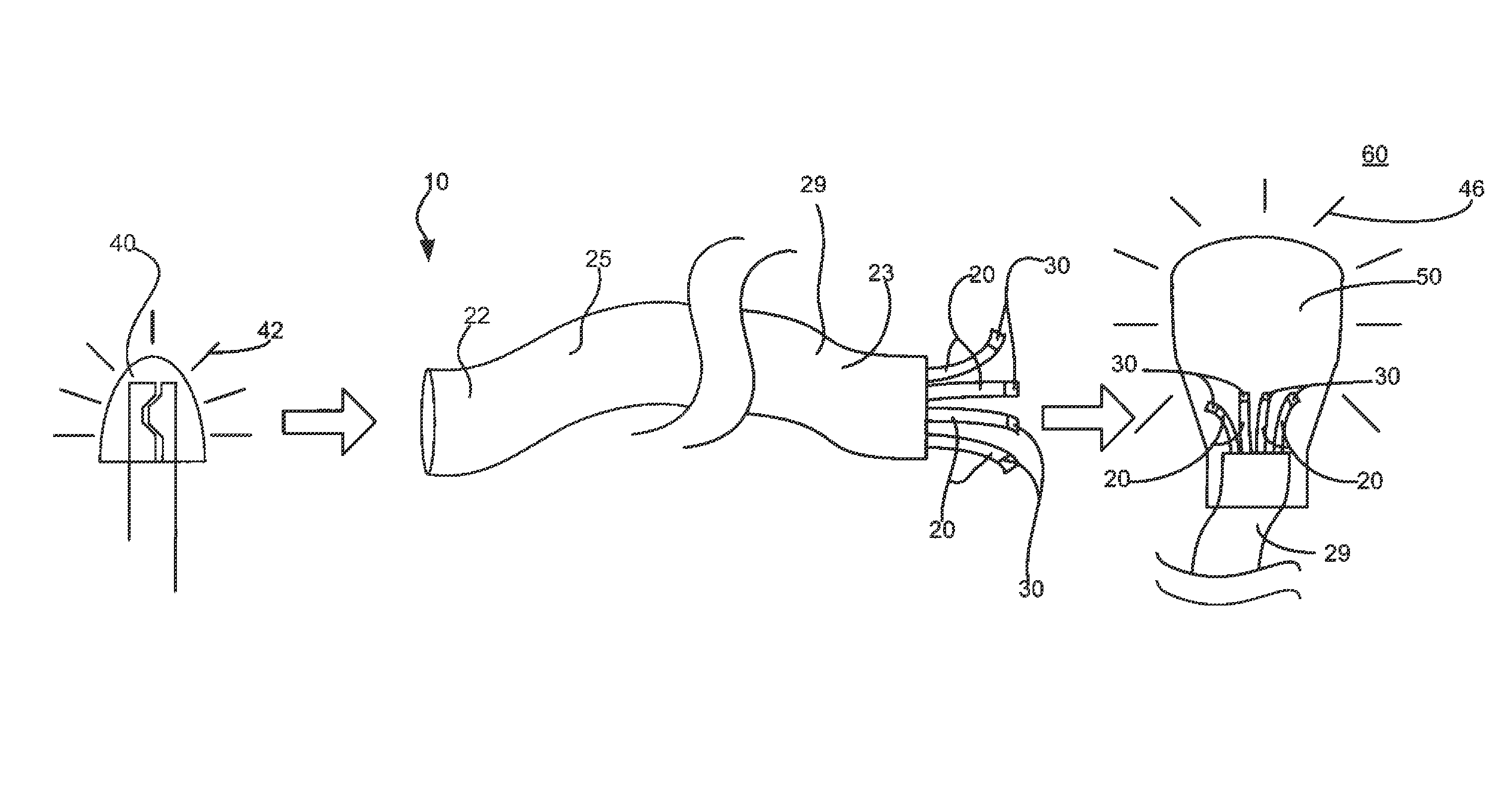
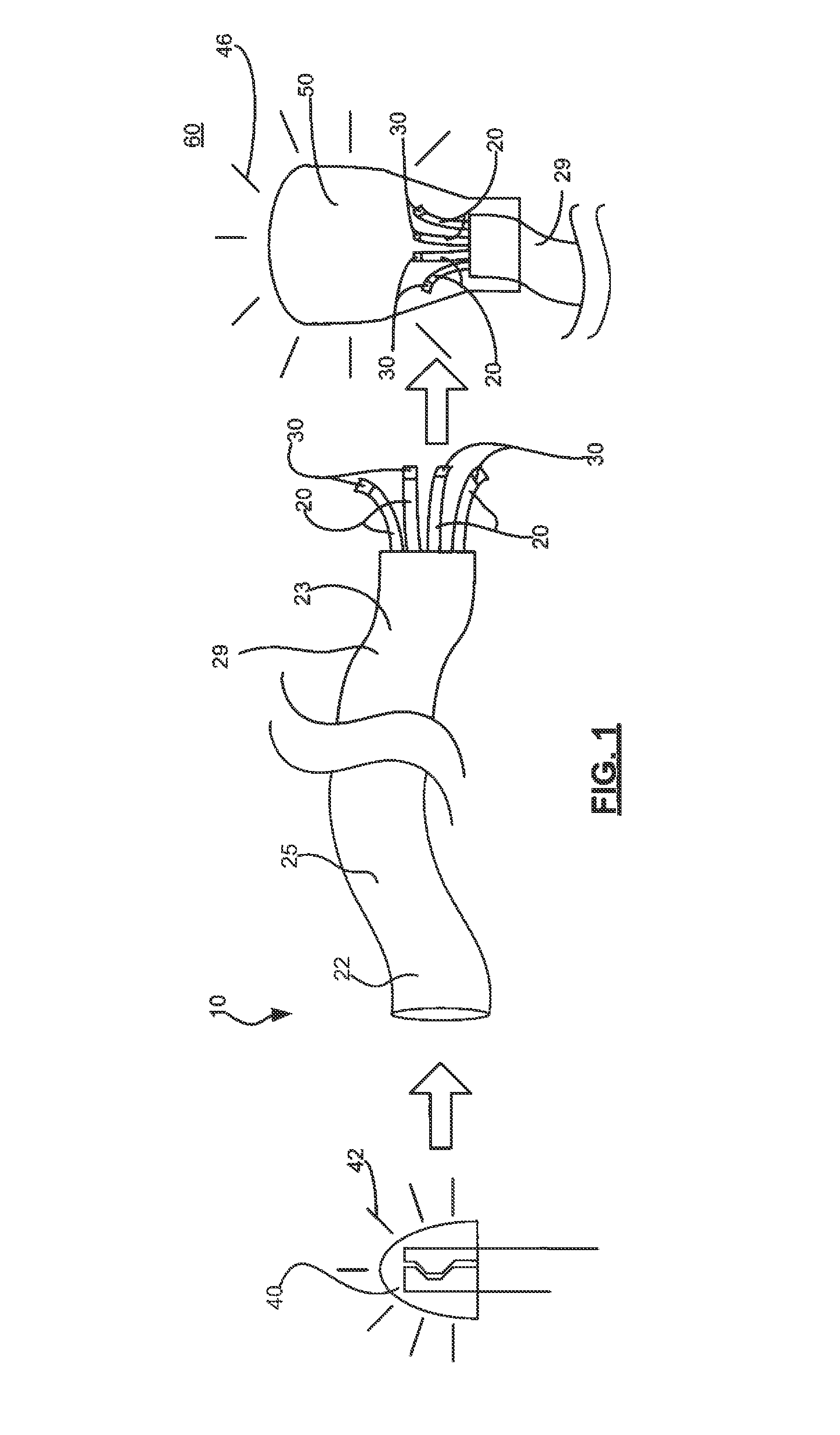
[0008]With the foregoing in mind, embodiments of the present invention are related to a remote light wavelength conversion device that receives a source light emitted from a light source in one wavelength range, transmit the source light to a remote location, and converts the source light into a converted light within a converted wavelength range to illuminate a space at or before the remote location. The remote light wavelength conversion device of an embodiment of the present invention may also advantageously perform the wavelength conversion operation away from a heat generating light source, with a minimal conversion area. By providing a remote light wavelength conversion device that advantageously converts light at a remote location, away from the heat generating light source, the remote wavelength conversion device according to an embodiment of the present invention may beneficially possess characteristics of reduced complexity, size, and manufacturing expense.

Problems solved by technology

However, LEDs and other lighting elements may generate heat during operation.
Applying a conversion material directly upon a lighting element for light source) may cause the coating to be exposed to an excessive amount of heat, resulting in decreased operational efficiency of the conversion material, and possible breakdown of the material.
However, physical integration of the conversion material and the light source may prohibit the ability to adjust the composition of the emitted light, except through the use of filters that may inefficiently absorb the emitted light.
However, coating the entire surface of the enclosure may require copious amounts of conversion coating materials, increasing the production cost of a lighting device employing this method.
However, the lens may need to be large to allow light to pass with a sufficiently wide projection angle, thereby requiring a large surface area.
Although applying a conversion coating to a lens may be an improvement over applying the coating to an entire enclosure, the lens-based proposed solution is still not optimal.

Method used


Image

  • Remote light wavelength conversion device and associated methods
  • Remote light wavelength conversion device and associated methods
  • Remote light wavelength conversion device and associated methods

Examples


Embodiment Construction

[0029]The present invention will now be described more fully hereinafter with reference to the accompanying drawings, in which preferred embodiments of the invention are shown. This invention may, however, be embodied in many different forms and should not be construed as limited to the embodiments set forth herein. Rather, these embodiments are provided so that this disclosure will be thorough and complete, and will fully convey the scope of the invention to those skilled in the art. Those of ordinary skill in the art realize that the following descriptions of the embodiments of the present invention are illustrative and are not intended to be limiting in any way. Other embodiments of the present invention will readily suggest themselves to such skilled persons having the benefit of this disclosure. Like numbers refer to like elements throughout.

[0030]In this detailed description of embodiments of the present invention, a person skilled in the art should note that directional terms...


PUM


Abstract

A remote light wavelength conversion device is provided for converting a source light emitted from a light source within a source wavelength range into a converted light within a converted wavelength range. The remote light wavelength conversion device may include a waveguide and a color conversion optic. The waveguide may include a first end and a second end and the color conversion optic may be adjacently located at the second end of the waveguide. The color conversion optic may convert the source light transmitted through the waveguide to the converted light.

Description

FIELD OF THE INVENTION[0001]The present invention relates to the field of light conversion devices and, more specifically, to including a color conversion material with a waveguide to remotely convert light and illuminate a space, and associated methods.BACKGROUND OF THE INVENTION[0002]Lighting devices that include a conversion material may conveniently allow the conversion of a source light emitted from a light source into light of a different wavelength range. Often, such a conversion may be performed by using a luminescent, fluorescent, or phosphorescent material. The wavelength conversion materials may sometimes be included in the bulk of another material, applied to a lens or optic, or otherwise located in line with the light emitted from light source. In some instances the conversion material may be applied to the light source itself. A number of disclosed inventions exist that describe lighting devices that utilize a conversion material applied to an LED to convert light with...

Claims


Application Information

Patent Timeline
Patent Type & Authority Patents(United States)
IPC IPC(8): F21V9/16
CPCF21V9/16F21K9/56F21V2200/13F21K9/64F21V9/30
Inventor MAXIK, FREDRIC S.BRETSCHNEIDER, ERICSOLER, ROBERT R.BARTINE, DAVID E.
Owner LIGHTING SCI GROUP
Why Eureka
Try Eureka