Comparison circuits

a technology of comparator circuit and comparator, which is applied in the field of comparator circuit, can solve problems such as increasing the size of analog-to-digital converters

Active Publication Date: 2013-08-20
MEDIATEK INC
View PDF2 Cites 9 Cited by
  • Summary
  • Abstract
  • Description
  • Claims
  • Application Information

AI Technical Summary

Problems solved by technology

If it is desired to provide several ranges for input signal digitization, a pluralit...

Method used


Image

  • Comparison circuits
  • Comparison circuits
  • Comparison circuits

Examples


Embodiment Construction

[0018]The following description is of the best-contemplated mode of carrying out the invention. This description is made for the purpose of illustrating the general principles of the invention and should not be taken in a limiting sense. The scope of the invention is best determined by reference to the appended claims.

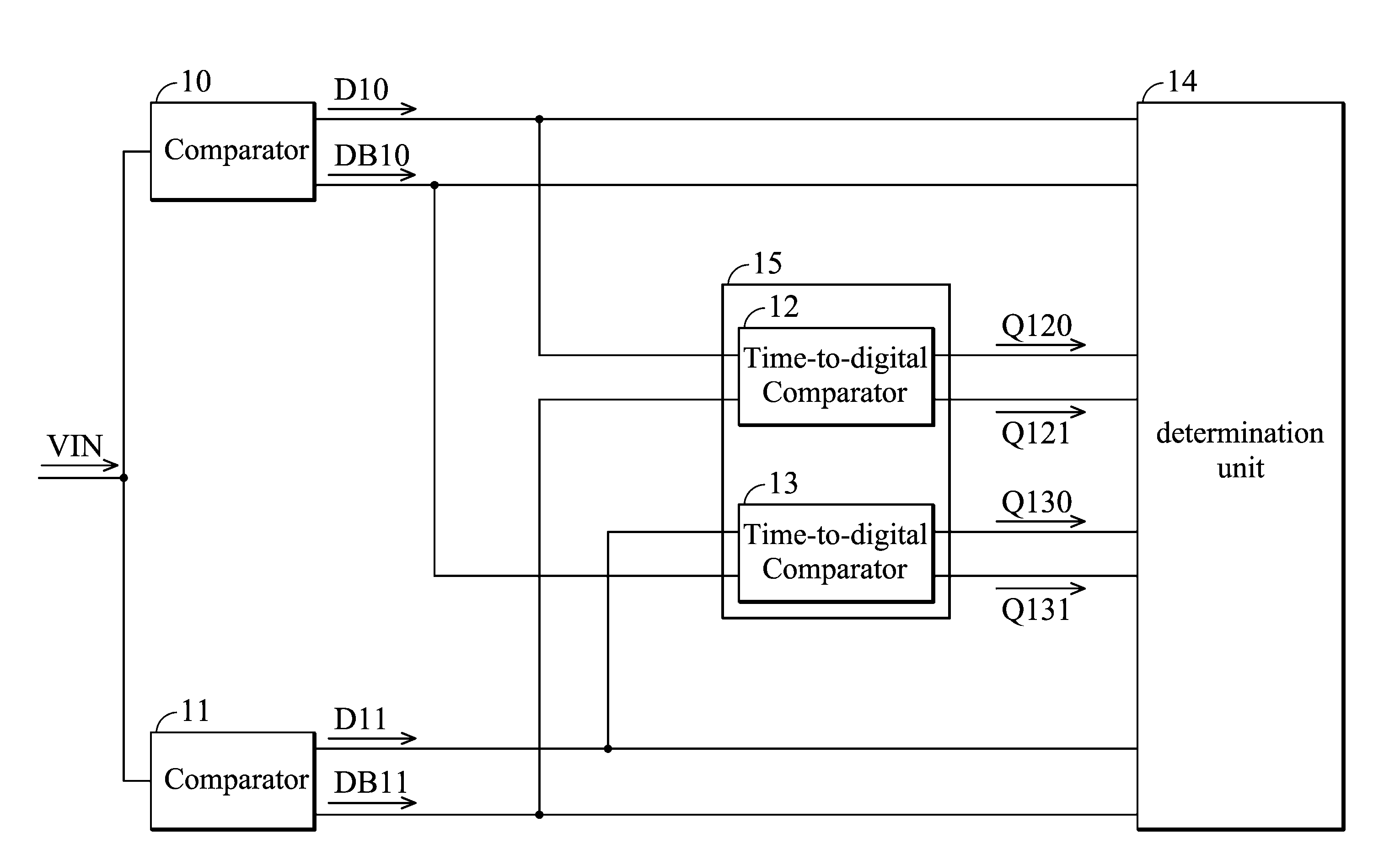
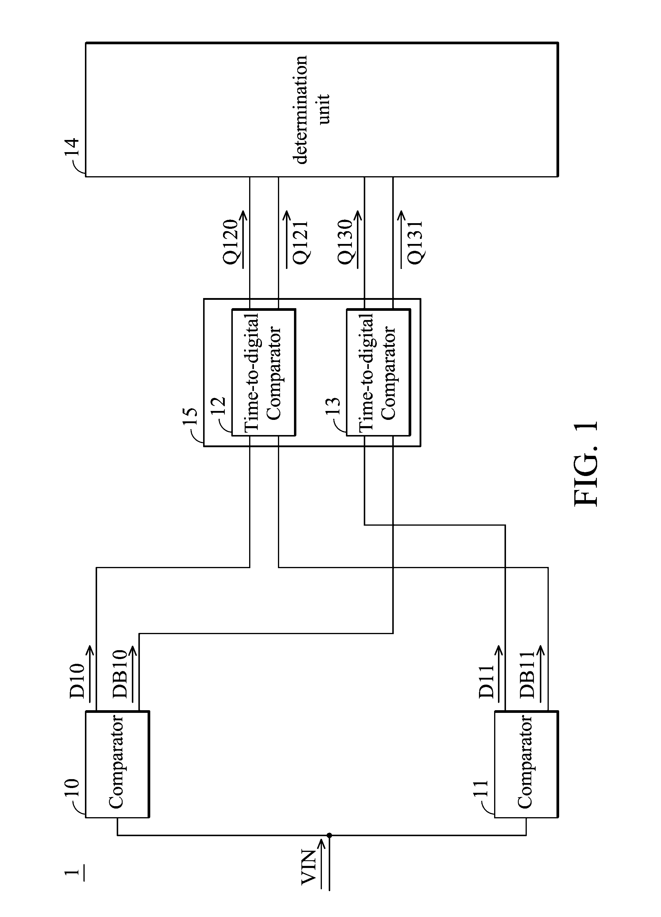
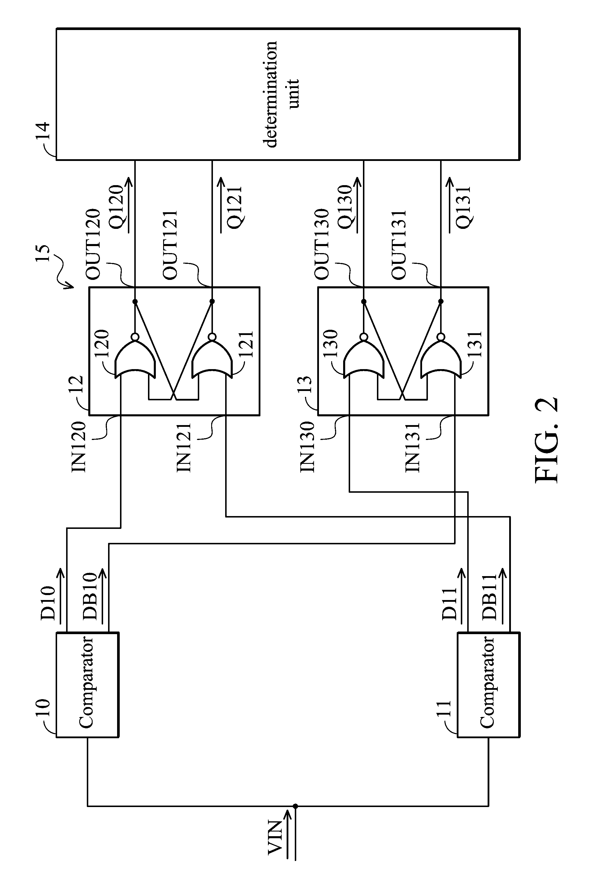
[0019]Comparison circuits are provided. In an exemplary embodiment of a comparison circuit in FIG. 1, a comparison circuit 1 comprises comparators 10 and 11, time-to-digital comparators 12 and 13, and a determination unit 14. The comparator 10 has a built-in offset voltage (or intrinsic offset) Voffset10, while the comparator 11 has a built-in offset voltage (or intrinsic offset) Voffset11. Both of the comparators 10 and 11 receive an input signal VIN. The comparator 10 performs a comparison operation to the input signal VIN based on the offset voltage Voffset10 to generate comparison signals D10 and DB10, wherein the comparison signal DB10 is inverse to the comparison...


PUM


Abstract

A comparison circuit is provided and includes first and second comparators and a first time-to-digital comparator. The first comparator with a first offset voltage receives an input signal and generates a first comparison signal and a first inverse comparison signal. The second comparator receives the input signal and generates a second comparison signal and a second inverse comparison signal. The first offset voltage is larger than the second offset voltage. The first time-to-digital comparator receives the first comparison signal and the second inverse comparison signal and generates first and second determination signals according to the first comparison signal and the second inverse comparison signal. The first and second determination signals indicate whether a voltage of the input signal is larger than a first middle voltage. The first middle voltage is equal to a half of the sum of the first offset voltage and the second offset voltage.

Description

BACKGROUND OF THE INVENTION[0001]1. Field of the Invention[0002]The invention relates to a comparison circuit, and more particularly to a comparison circuit with an offset averaging scheme.[0003]2. Description of the Related Art[0004]Comparators are widely applied for analog-to-digital conversion. In a conventional analog-to-digital converter, three comparators are required to digitize the input signal into four ranges. Each of the three comparators has a threshold voltage, and the three threshold voltages comprise the largest one among the three threshold voltages, the smallest one among the three threshold voltages, and the middle one between the largest threshold voltage and the smallest threshold voltage. Thus, the four ranges are: the range higher than the largest threshold voltage, the range between the largest threshold voltage and the middle threshold voltage, the range between the middle threshold voltage and the smallest threshold voltage, and the range lower than the smal...

Claims


Application Information

Patent Timeline
IPC IPC(8): H03M1/12
CPCH03M1/50H03M1/206H03M1/365H03M1/12H03M2201/4233H03M1/00
Inventor SHU, YUN-SHIANG
Owner MEDIATEK INC
Why Eureka
Try Eureka