
Non-linear common coarse delay system and method for delaying data strobe

a delay system and non-linear technology, applied in the field of electronic data storage systems and methods, can solve the problems of large delay cells for fine delays, increasing cycle delay, prior art methods only address pvt, etc., to increase the range of quarter cycle delay, simplify the construction of coarse delay, and reduce the overhead

Active Publication Date: 2013-05-28
AVAGO TECH INT SALES PTE LTD
View PDF9 Cites 9 Cited by
  • Summary
  • Abstract
  • Description
  • Claims
  • Application Information

AI Technical Summary

Benefits of technology

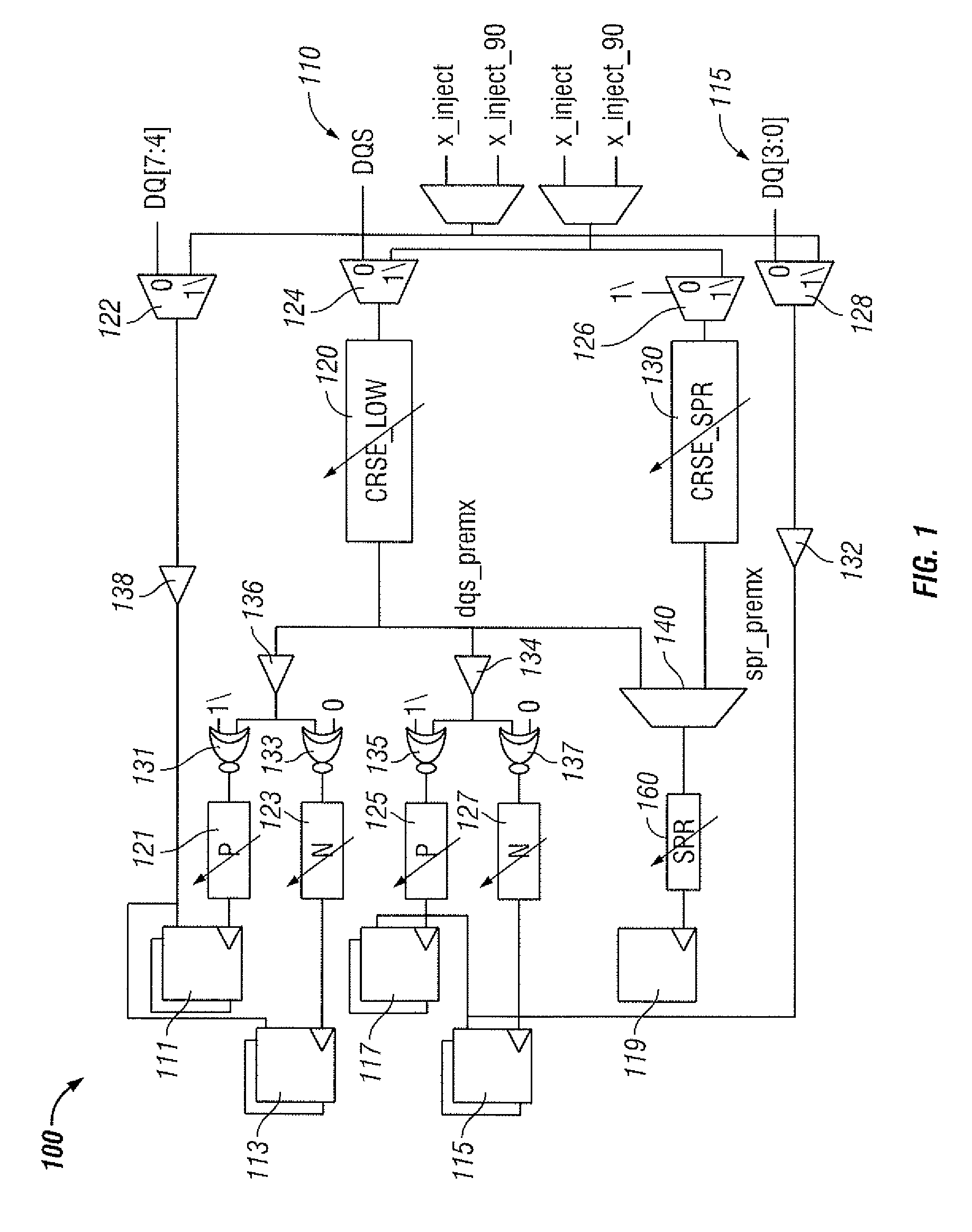
[0008]It is another aspect of the disclosed embodiments to provide for an improved non-linear common coarse delay system and method for delaying a data strobe utilizing a common coarse delay and a fine delay to a quarter-cycle delay in order to preserve fine delay accuracy.
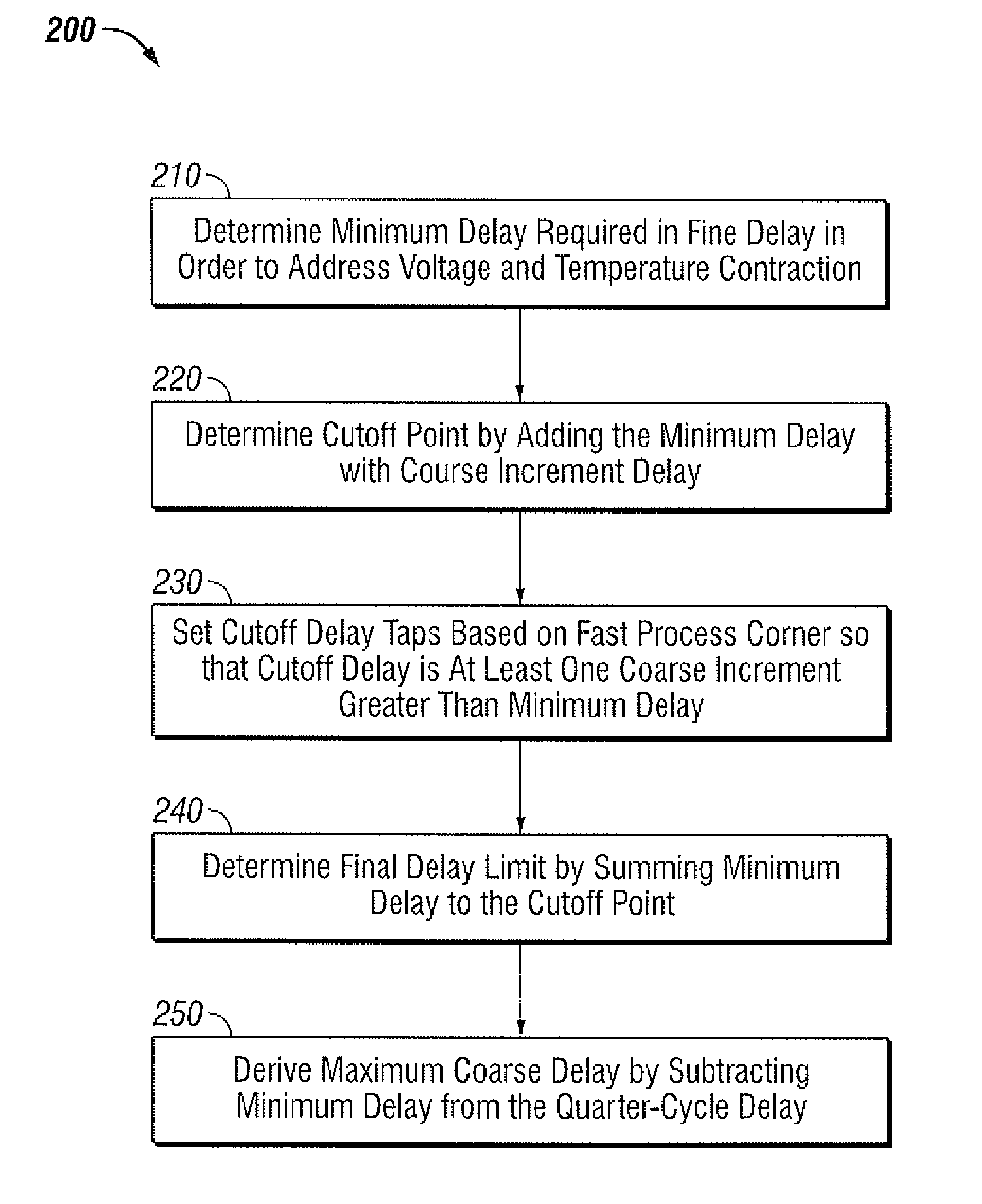
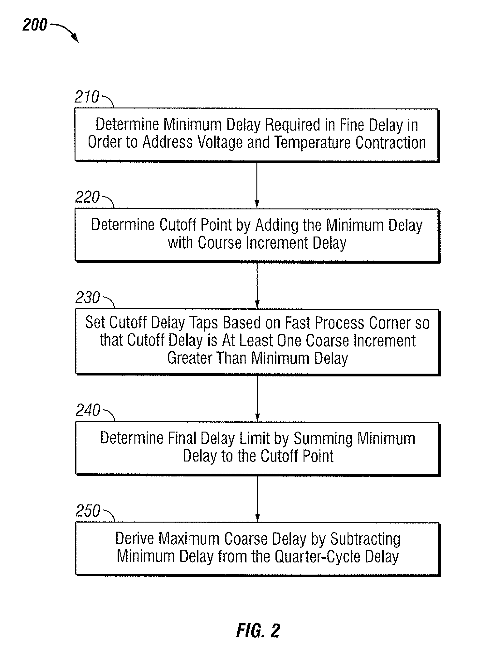
[0014]The common coarse delay can be employed to achieve the bulk of the delay with minimum area overhead and the fine delays are smaller and provide the accuracy. The common coarse delay possess large delay steps with no requirement for a linear continuity of delay increments from the fine delays to the coarse delay in order to greatly simplify the construction of the coarse delay. Such an approach increases the range of the quarter cycle delay on the DQS with minimum area overhead by using the common coarse delay that can be made up of inaccurate but area dense components.

Problems solved by technology

As frequency of operation decreases, the quarter-cycle delay increases and consequently the area overhead of four delays cells becomes a large percentage of the overall PHY area.
Such fine delays require large delay cells to achieve both the bulk delay and the fine granularity.
Additionally, the fine delay must be pre-constructed utilizing either discrete gates or many simple standard cells such as, for example, NAND gates, which can be time consuming to construct such a delay that can maintain linearity (uniform delay steps) across its entire range.
Furthermore, prior art methods only address PVT (Process, Voltage, Temperature) compensation of the fine delays or of a standalone coarse plus fine delay that combine to be a single linearly incrementing delay.

Method used


Image

  • Non-linear common coarse delay system and method for delaying data strobe
  • Non-linear common coarse delay system and method for delaying data strobe
  • Non-linear common coarse delay system and method for delaying data strobe

Examples


Embodiment Construction

[0021]The particular values and configurations discussed in these non-limiting examples can be varied and are cited merely to illustrate at least one embodiment and are not intended to limit the scope thereof.

[0022]The embodiments now will be described more fully hereinafter with reference to the accompanying drawings, in which illustrative embodiments of the invention are shown. The embodiments disclosed herein can be embodied in many different forms and should not be construed as limited to the embodiments set forth herein; rather, these embodiments are provided so that this disclosure will be thorough and complete, and will fully convey the scope of the invention to those skilled in the art. Like numbers refer to like elements throughout. As used herein, the term “and / or” includes any and all combinations of one or more of the associated listed items.

[0023]The terminology used herein is for the purpose of describing particular embodiments only and is not intended to be limiting o...


PUM


Abstract

A non-linear common coarse delay system and method for delaying a data strobe in order to preserve fine delay accuracy and compensate PVT (Process, Voltage, and Temperature) variation effects. A common coarse delay and a fine delay can be initialized to a quarter-cycle delay for shifting a read output DQS (Data Queue Strobe) associated with a memory device in order to sample a read output DQ (Data Queue) within a physical layer. The fine delay can be programmed from minimum to maximum delay with fixed linear increments at each delay step in order to determine the resolution and accuracy of the delay. An optimum delay size of both the coarse and the fine delay can be determined based on an application slowest frequency of operation. A spare coarse delay and a functional coarse delay can be trained in association with a spare fine delay and the functional fine delay can be updated in order to monitor the process, voltage, and temperature variation effects.

Description

TECHNICAL FIELD[0001]Embodiments are generally related to electronic data storage systems and methods. Embodiments are also related to a physical layer solution for sampling read data from a source synchronous memory. Embodiments are additionally related to systems and methods for delaying a data strobe. Embodiments are further related to the compensation of PVT (Process, Voltage, and Temperature) effects.BACKGROUND OF THE INVENTION[0002]High-speed synchronous systems generally require a tightly controlled clock timing allowance for high performance operation. With source-synchronous interfaces, data and clock transport from a transmitter to a receiver, and the receiver interface employs the clock to latch the accompanying data. The device that transmits data also generates a data strobe signal that travels toward the receiving device along with the data signals. Such source-synchronous signaling eliminates problems associated with common clock systems such as propagation delay, clo...

Claims


Application Information

Patent Timeline
Patent Type & Authority Patents(United States)
IPC IPC(8): G06F17/50
CPCG11C7/04G11C7/1072G11C7/222G11C11/4076
Inventor MAGEE, TERENCE J.PAULSON, CHRISTOPHER D.KONG, CHENG-GANG
Owner AVAGO TECH INT SALES PTE LTD
Learn More