Fan impeller and fan motor

a technology of impeller and fan, which is applied in the direction of piston pumps, marine propulsion, vessel construction, etc., can solve the problems of reducing the airflow volume of the fan and lowering the cooling efficiency below the inherent performance of the fan motor, and achieves the effect of maximum cooling efficiency and high cooling efficiency

Inactive Publication Date: 2006-01-19
NIDEC CORP
View PDF6 Cites 9 Cited by
  • Summary
  • Abstract
  • Description
  • Claims
  • Application Information

AI Technical Summary

Benefits of technology

[0009] An object of the present invention is to realize a fan motor that can be used for ultra-compact devices such as cellular phones, and that is ultrasmall in size and has high cooling efficiency, as well as to realize an impeller that is used for a fan motor of this sort. Another object of the present invention is to make available a fan motor capable of realizing maximum cooling efficiency with minimum air-inlet area, as well as to make available an impeller that is used for such a fan motor.

Problems solved by technology

The windage loss on the wall surface can decrease airflow volume from the fan and lower the cooling efficiency below the inherent performance of the fan motor.

Method used


Image

  • Fan impeller and fan motor
  • Fan impeller and fan motor
  • Fan impeller and fan motor

Examples


Embodiment Construction

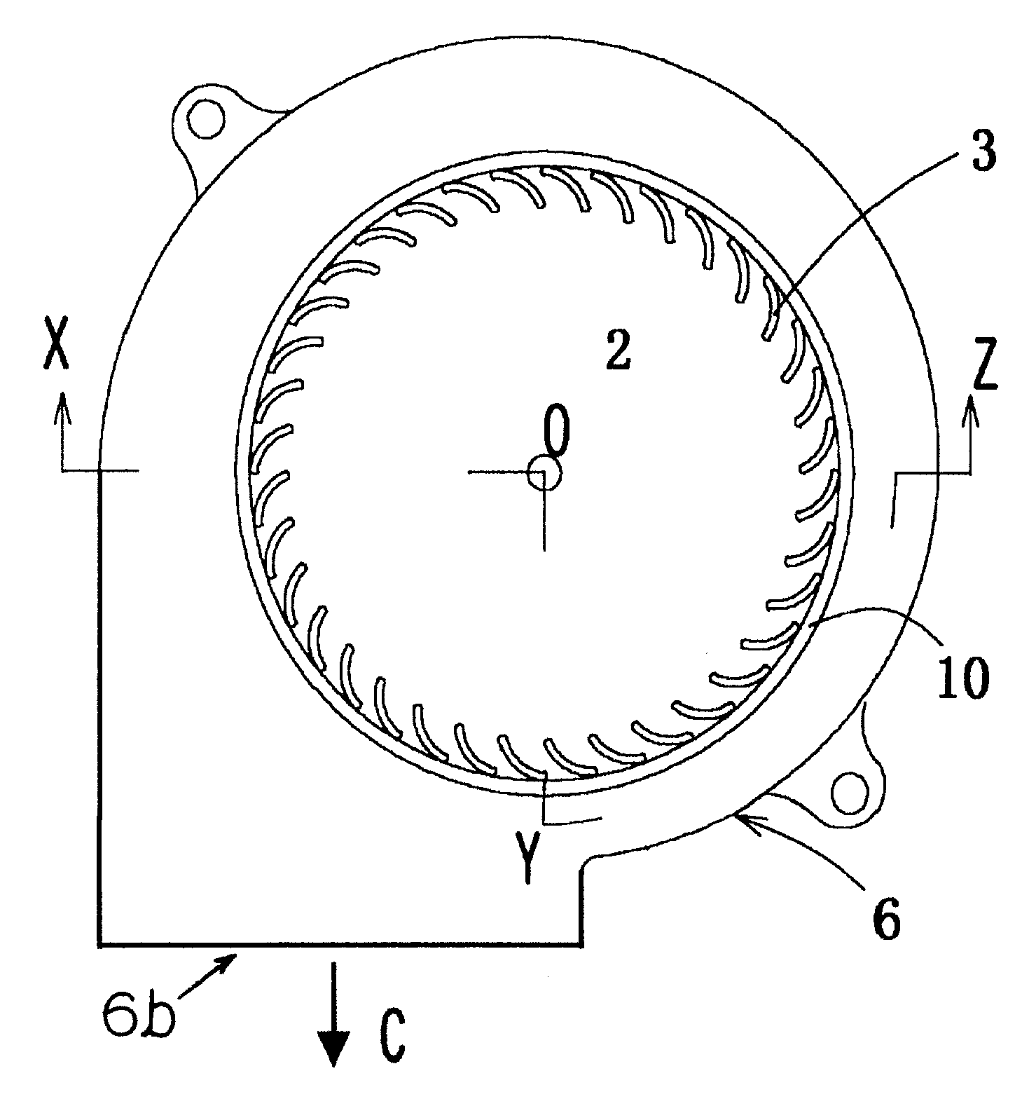
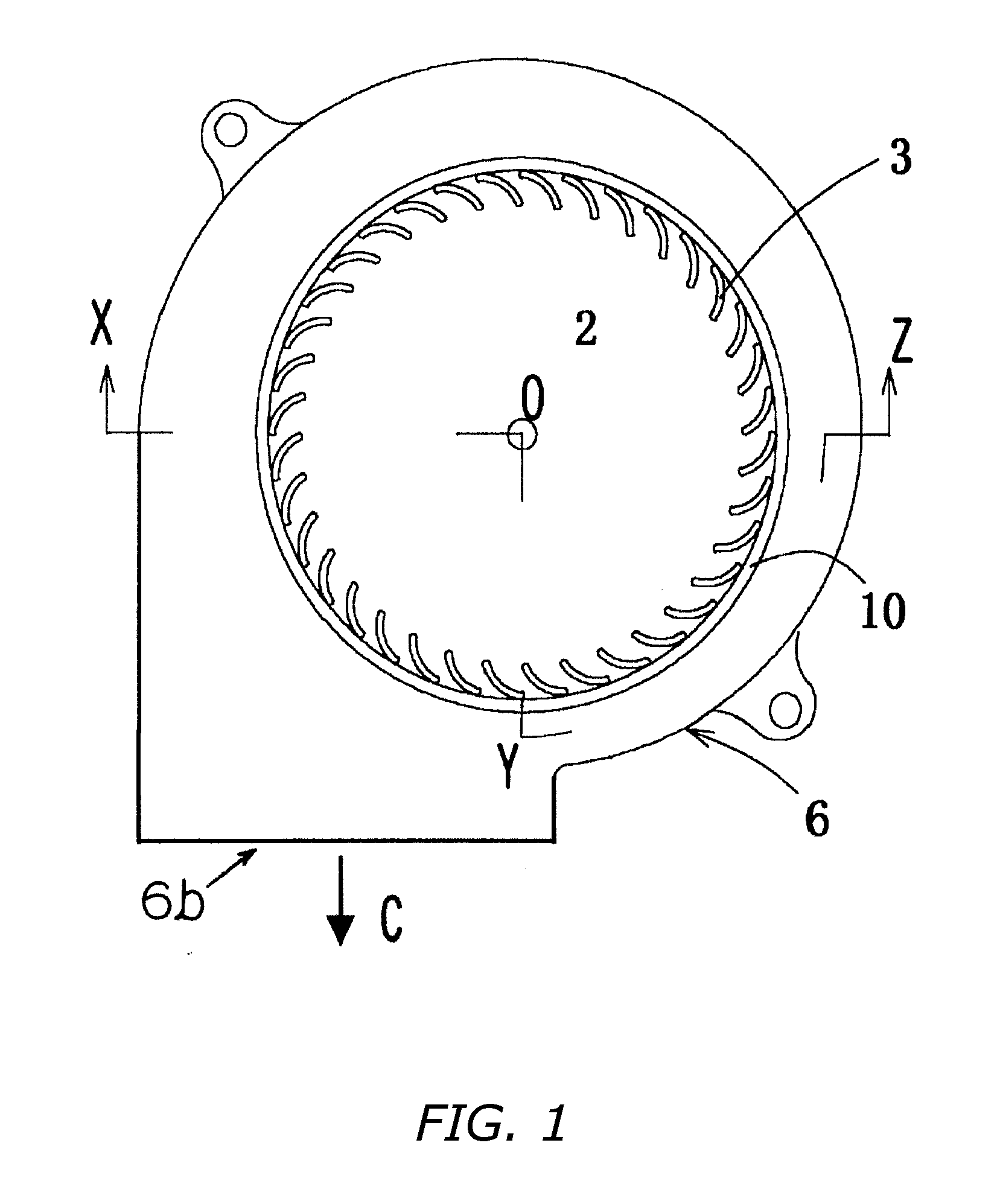
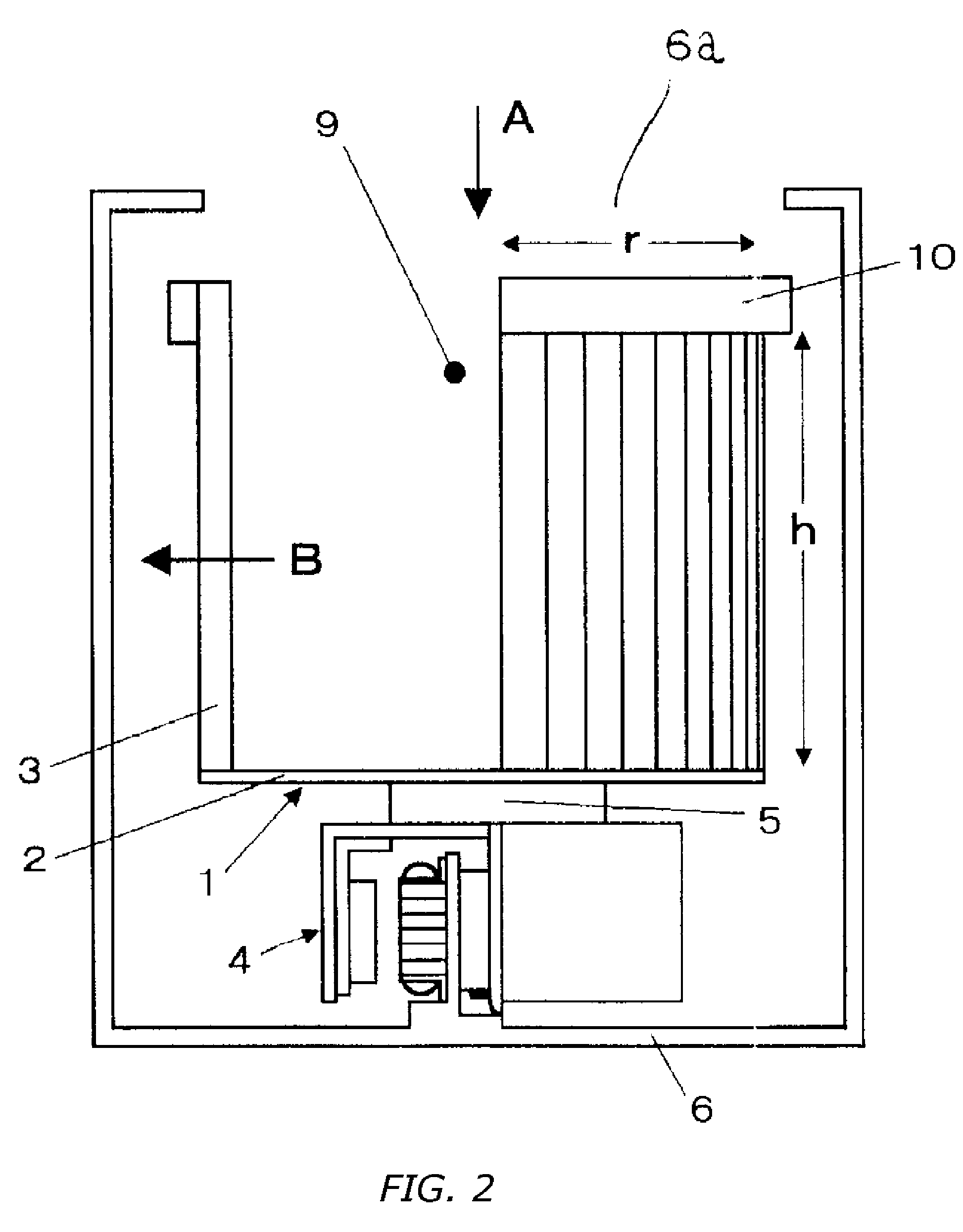
[0029] Reference is made to FIG. 1, which is a plan view of a centrifugal fan motor according to an embodiment of the present invention, and to FIG. 2, which is a vertical cross section, taken along the line X-O-Y-Z in FIG. 1. The vertical direction in FIG. 2 corresponds to the orientation of the rotational axis of the centrifugal fan motor. Though upper and lower sides are defined according to FIG. 2 in the following explanation, the definitions are for convenience of explanation and are not meant to imply restrictions on the actual attachment posture of the fan motor.

[0030] This fan motor includes an impeller component 1, a motor component 4 and a housing 6. The impeller component 1 and the motor component 4 are disposed axially stacked and connected to each other, and these interconnected components are contained in the housing 6. The rotational axis of this centrifugal fan motor is indicated by O in FIG. 1.

[0031] Reference is now made to FIG. 3, which shows the impeller compon...


PUM


Abstract

Small, high-performance centrifugal fan for cooling portable electronic devices. The centrifugal fan motor employs a cantilever-type impeller constituted by an impeller blade unit that includes a lower endwall portion at axial one end, having a wall surface for breaking the flow of air along the rotational axis, and an opening at the other axial end. The impeller is configured so that the radius r to the outer circumference of the impeller blade unit is smaller than the axial height h of the impeller. When an airflow that enters through the impeller opening is forced out towards outer periphery of the impeller blade unit, windage loss at the wall surface of the lower endwall portion of the impeller is reduced, which realizes high-efficiency cooling performance that complements motor performance.

Description

BACKGROUND OF INVENTION [0001] 1. Technical Field [0002] The present invention relates to cooling-fan motors and impellers that are used in electronic devices and the like. More specifically, the present invention relates to fan motors that must generate high static pressure and ample airflow volume, and to cantilever-type impellers that are used in such fan motors. [0003] 2. Description of the Related Art [0004]FIG. 8 is a plan view of a conventional centrifugal fan motor. FIG. 9 is a vertical cross section along the line X1-O1-Y1-Z1 in FIG. 8. This centrifugal fan motor includes a motor component 104 for generating rotational driving force, an impeller component 101 for generating airflow, and a housing 106. This centrifugal fan motor has a rotational axis 01 shown in FIG. 8. [0005] The impeller component 101 is located around the outer periphery of the motor component 104 and includes a lower end wall 102 and blades 103. The lower end wall 102 is an annular plate member located s...

Claims


Application Information

Patent Timeline
Patent Type & Authority Applications(United States)
IPC IPC(8): F01D1/02
CPCF01D1/02F04D25/0613F04D29/283
Inventor TAMAGAWA, TORUYOSHIDA, YUSUKE
Owner NIDEC CORP
Why Eureka
Try Eureka