Battery and electronic apparatus

a battery and electronic technology, applied in the field of batteries and electronic devices, can solve the problems of difficult to provide a recess for recognition of batteries, limit the thicknesswise reduction of the battery accommodating chamber, etc., and achieve the effects of enhancing the convenience of use, enhancing the strength of a corner portion of the case which is liable to strike on an external body, and prolonging the service li

Inactive Publication Date: 2013-04-02
SONY CORP
View PDF15 Cites 2 Cited by
  • Summary
  • Abstract
  • Description
  • Claims
  • Application Information

AI Technical Summary

Benefits of technology

[0012]It is an object of the present invention to provide a battery of a reduced thickness and an electronic apparatus of a reduced size which are superior in convenience.
[0033]With each of the electronic apparatus, the portions of the contact pieces of the electronic apparatus side connector section can be positioned at a location higher than the lower face of the case accommodating chamber. Consequently, the electronic apparatus side connector section does not project downwardly farther than the lower face of the case accommodating chamber. This is advantageous in suppressing the dimension of the battery accommodating chamber in the upward and downward direction.

Problems solved by technology

Consequently, there is a limitation to reduction of the dimension of the battery accommodating chamber in the thicknesswise direction.
Therefore, it is difficult to provide a recess for recognition of a battery characteristic or property which is recessed inwardly of the case.

Method used


Image

  • Battery and electronic apparatus
  • Battery and electronic apparatus
  • Battery and electronic apparatus

Examples


first embodiment

[0105]A first embodiment of the present invention is described below with reference to the drawings.

[0106]It is to be noted that, in some of the drawings, a plurality of straight lines or curved lines are drawn on a surface of a member or a portion of a member in order to indicate a cylindrical surface, a curved surface or an inclined surface. This similarly applies to the drawings which illustrate different embodiments of the present invention.

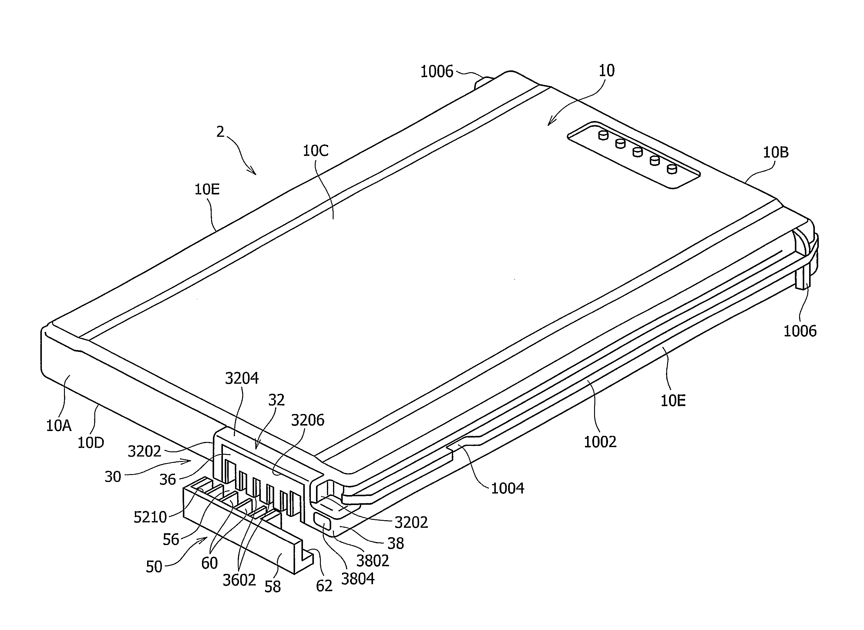
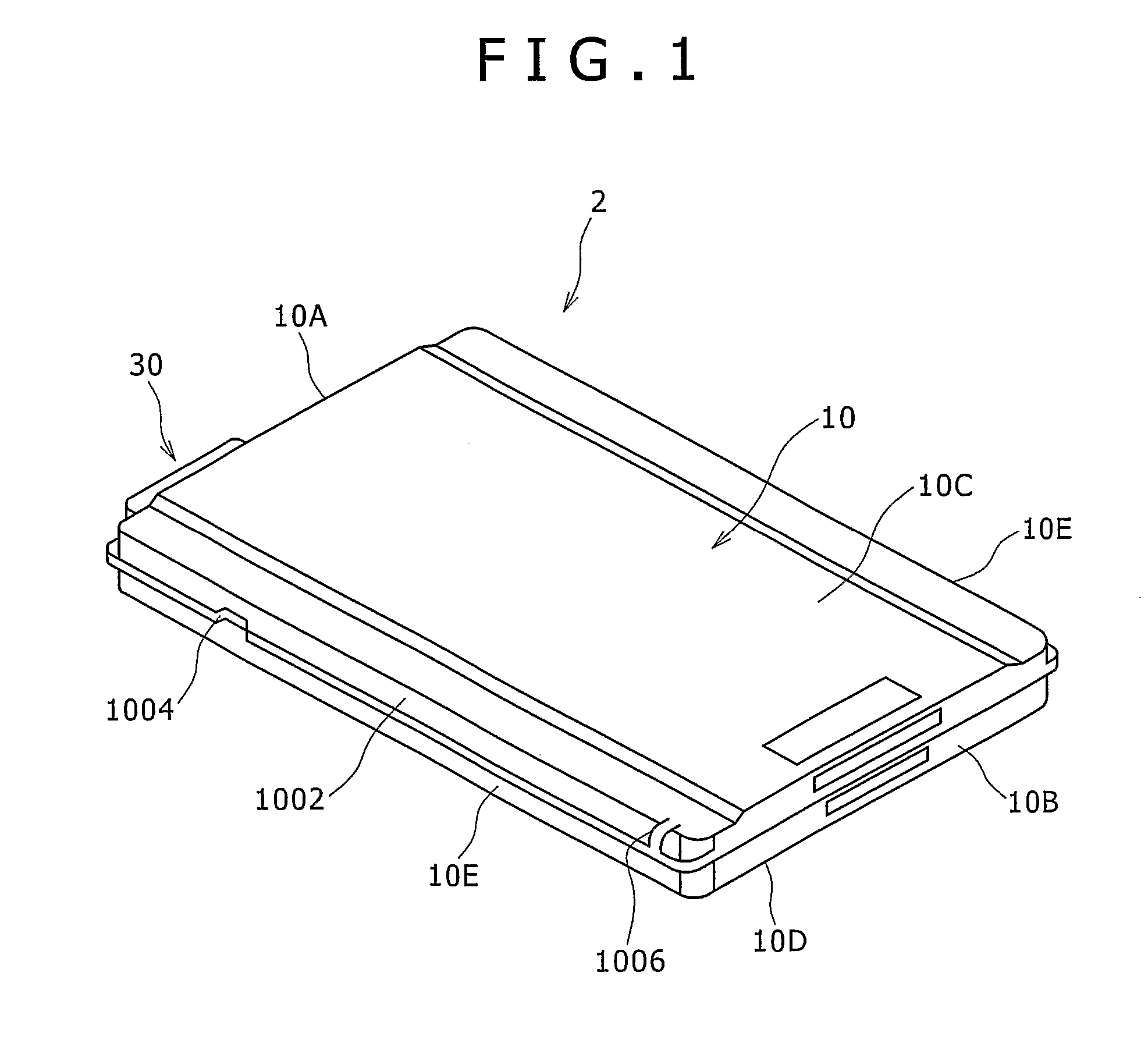
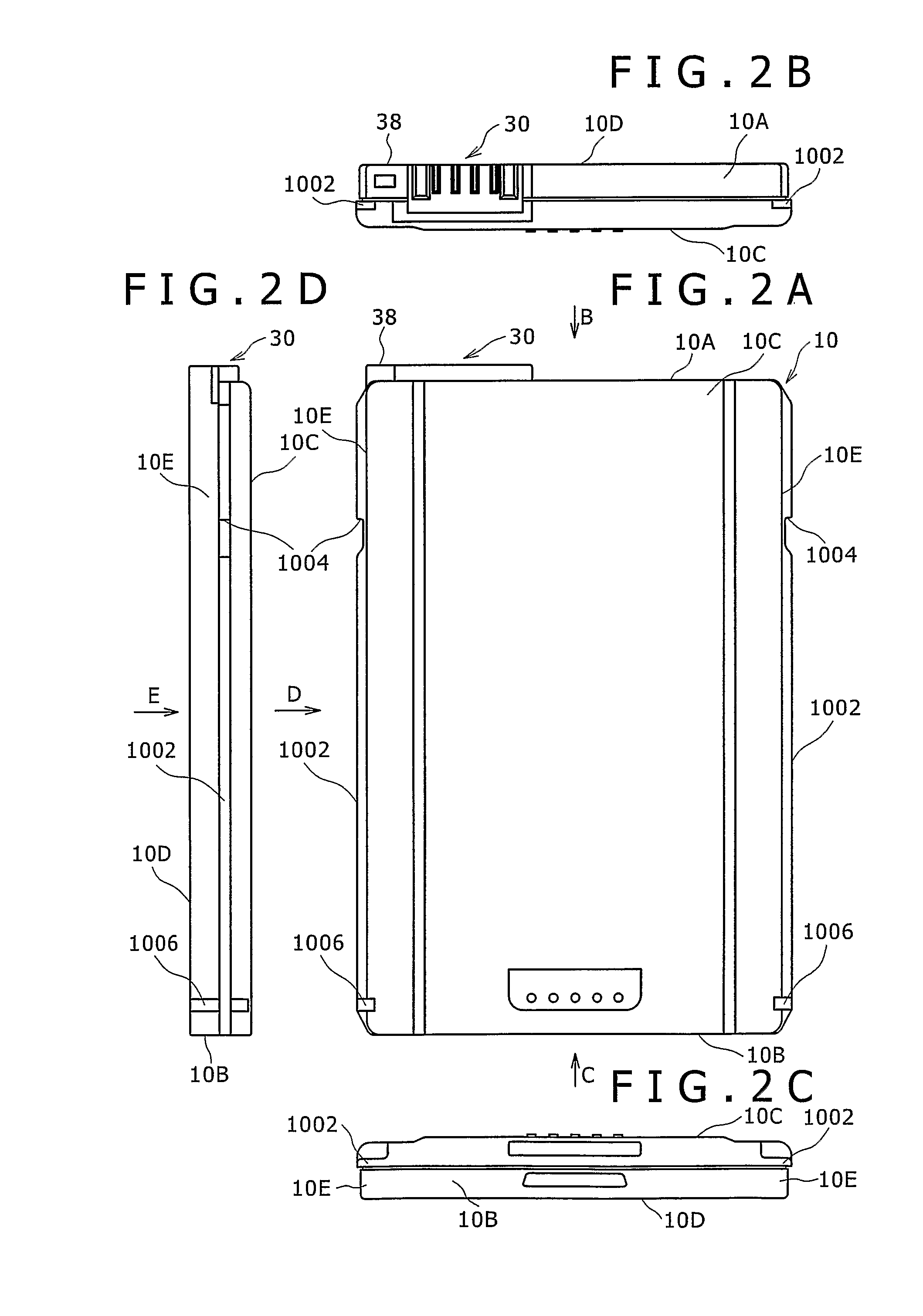
[0107]Referring first to FIGS. 1 and 2A to 2F, there is shown a first battery 2 according to the first embodiment of the present invention. The first battery 2 includes a case 10, one or more battery cells (not shown) accommodated in the case 10, and a connector section 30.

[0108]The case 10 is formed as a flattened substantially rectangular plate shape having a thickness, a width in a leftward and rightward direction having a greater dimension than the thickness and a length in a forward and backward direction having a greater dimension than ...

second embodiment

[0167]Now, a second embodiment of the present invention is described with reference to FIGS. 13A to 19.

[0168]The second embodiment is a modification to and is common in configuration to the first embodiment except the shape of the wall portion 38 for discrimination of a battery and the dimension of the battery in the thicknesswise direction.

[0169]Referring first to FIGS. 13A to 13C, the battery case 10 of the first battery 2 and the battery case 10 of the second battery 4 are formed equal in width and length to each other, but the battery case 10 of the second battery 4 has a greater thickness than the battery case 10 of the first battery 2.

[0170]The connector section 30 provided on the second battery 4 and the connector section 30 provided on the first battery 2 are formed in the same shape and structure, and the positions of them in the upward and downward direction on the front face 10A are the same location with reference to the engaging walls 1002 while the positions of them in...

third embodiment

[0185]Now, a third embodiment of the present invention is described with reference to FIGS. 20A to 20C and 21A to 21B.

[0186]The third embodiment is a modification to and is common in configuration to the first embodiment except the shape of the wall portion 38B for discrimination of a battery characteristic.

[0187]In the third embodiment, the wall portion 38B is formed integrally with one of the vertical walls 3202.

[0188]More particularly, referring to FIGS. 20A to 20C, that one of the vertical walls 3202 of the connector wall section 32 of the connector section 30 which is positioned rather near to the right end portion in the widthwise direction is formed so as to extend to the right end of the front face 10A, and the wall portion 38B is formed from the extension of the vertical wall 3202.

[0189]In other words, in the third embodiment, the right side vertical wall 3202 of the connector section 30 is formed from a left side portion of the wall portion 38B, and a right side portion of...


PUM

PropertyMeasurementUnit
thicknessaaaaaaaaaa
widthaaaaaaaaaa
lengthaaaaaaaaaa

Abstract

A battery and an electronic apparatus are disclosed by which it can be discriminated with a simple configuration whether or not the battery is of a thin type. The battery is configured such that a wall portion for discrimination of a battery characteristic which is swollen in a lengthwise direction and connects to a connector section is formed at a location of one of end faces positioned rather near to an end portion in a widthwise direction of a case of the battery.

Description

TECHNICAL FIELD[0001]This invention relates to a battery and an electronic apparatus in which a battery is removably loaded.[0002]The present invention contains subject matter related to Japanese Patent Application JP 2004-367149 filed in the Japanese Patent Office on Dec. 20, 2004, and the Japanese Patent Application JP 2004-369041 filed in the Japanese Patent Office on Dec. 21, 2004, entire contents of which being incorporated herein by reference.BACKGROUND ART[0003]A battery for being loaded in an electronic apparatus in related art is known which includes a case, a plurality of cylindrical battery cells accommodated in the case, and a battery side connector section provided on the case and connected to the battery cells. The battery is configured such that, when it is accommodated into a battery accommodating chamber of an electronic apparatus, the battery side connector section is connected to an electronic apparatus side connector section in the battery accommodating chamber.[...

Claims


Application Information

Patent Timeline
Patent Type & Authority Patents(United States)
IPC IPC(8): H01M6/02H01M2/34H01M2/10H01M2/02H01M50/296H01M50/588
CPCH01M2/021H01M2/34H01M2/0215Y02E60/10H01M50/588H01M50/296H01M50/10H01M50/572H01M50/20
Inventor HAGIWARA, HIDEKIKOBAYASHI, MICHIHITOKONNO, YOSHIHIROSHINTANI, SHOICHIMIYAJIMA, YOICHISAMESHIMA, TSUGIOTSUMURA, TOMOHIROKITAGAWA, KAZUHIROMIYAMORI, KIYOSHITAKESHITA, TOSHIOTAKAHASHI, ATSUSHIHOSOYA, NAOTOTSUCHIDA, YOSHIHISAAMATATSU, SEIYATAKAHASHI, NOBUTATSU
Owner SONY CORP
Why Eureka
Try Eureka