
Optical position detection device

a position detection and optical technology, applied in measurement devices, electromagnetic wave reradiation, instruments, etc., can solve the problem of inability to detect the respective positions of target objects located in the two spaces, and achieve the effect of simplifying the configuration of the position detecting light source and the second space configuration

Active Publication Date: 2013-04-02
COLUMBIA PEAK VENTURES LLC
View PDF7 Cites 27 Cited by
  • Summary
  • Abstract
  • Description
  • Claims
  • Application Information

AI Technical Summary

Benefits of technology

[0009]In this aspect of the invention, it is possible to adopt the configuration in which the position derivation section derives the position of the target object located in the second space based on the light receiving result in the second light detector, and detects the position of the target object located in the first space based on a difference between the light receiving result in the first light detector and the light receiving result in the second light detector. According to the configuration of this aspect of the invention, it is possible to perform the correction corresponding to the light receiving result in the second light detector on the light receiving result in the first light detector by a simple process of obtaining the difference.

Problems solved by technology

However, in the technology described in Document 1, since the detection result in the light detector is obtained as a sum of intensities of the detection light beams reflected by the respective target objects located in the two spaces, there arises a problem that detection of the respective positions of the target objects located in the two spaces is not achievable.

Method used


Image

  • Optical position detection device
  • Optical position detection device
  • Optical position detection device

Examples


Embodiment Construction

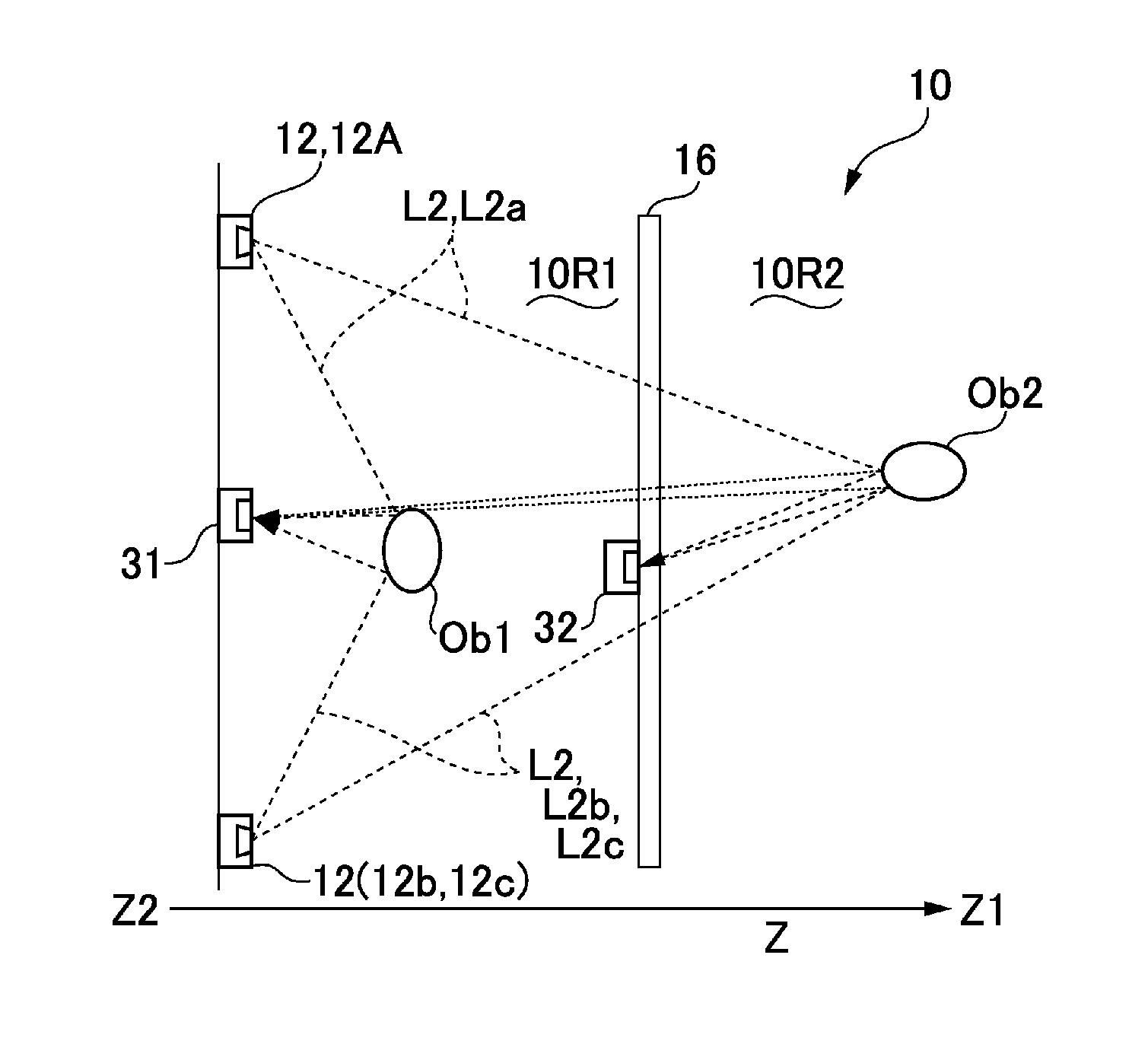
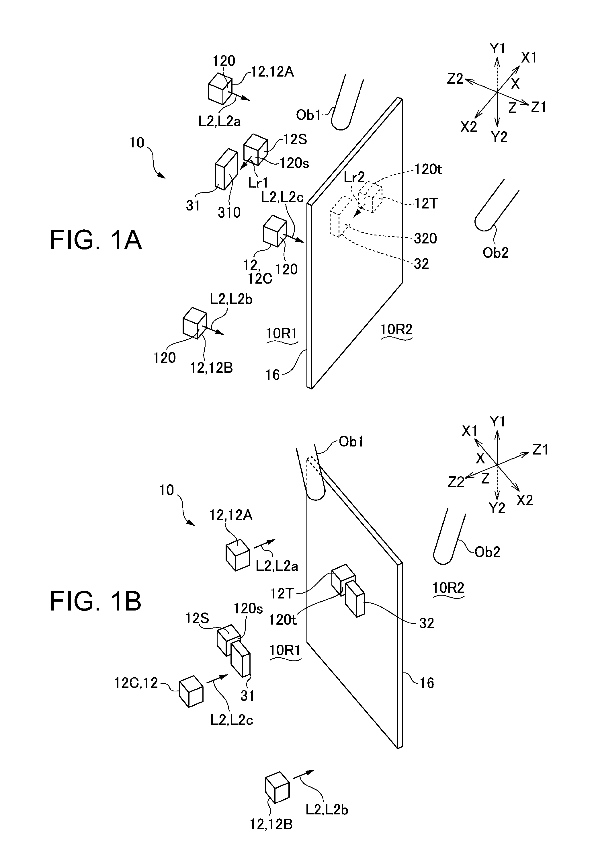
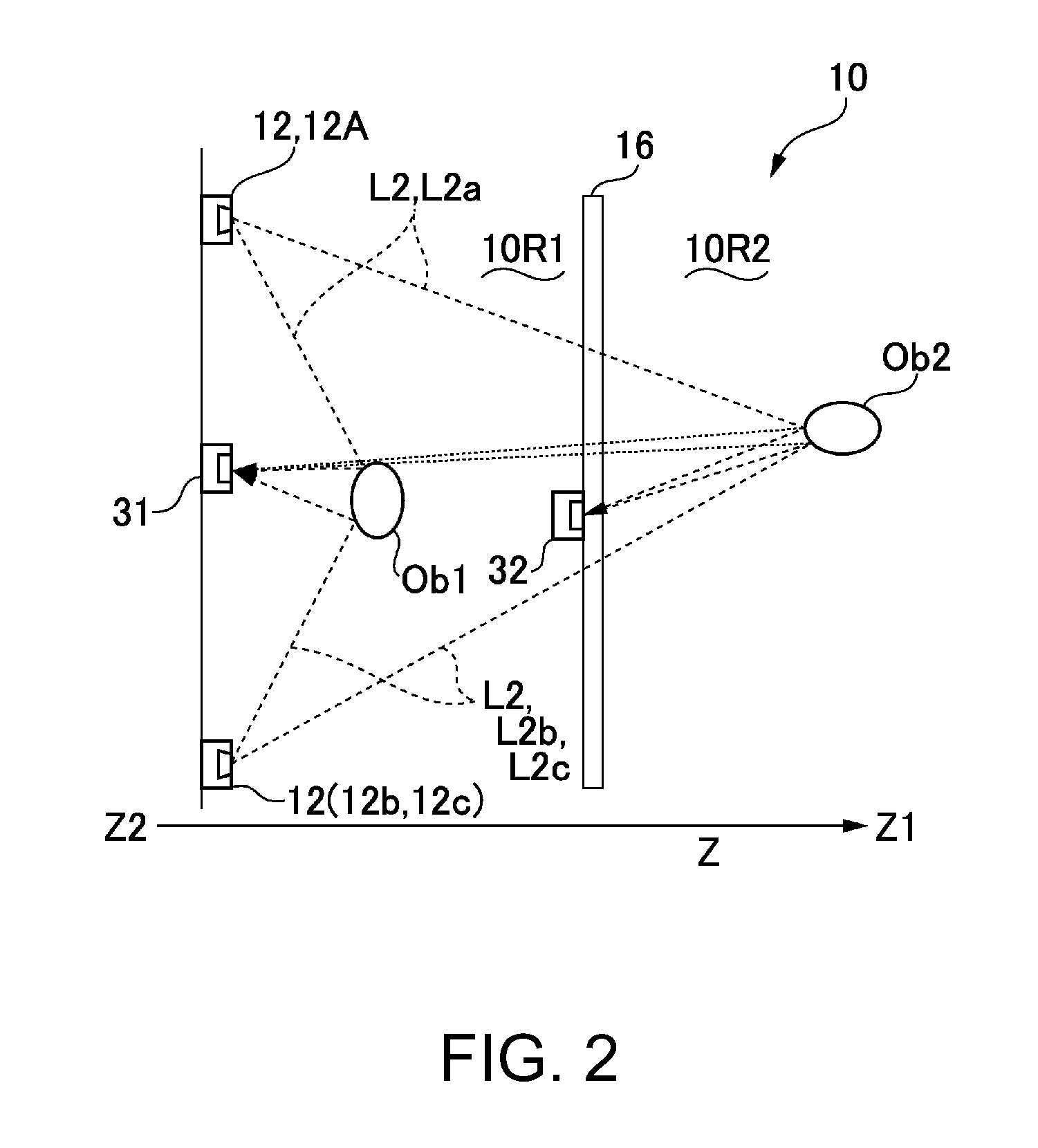
[0026]An embodiment of the invention will be explained in detail with reference to the accompanying drawings. It should be noted that in the following explanation it is assumed that directions intersecting with each other are X-axis direction, Y-axis direction, and Z-axis direction, respectively. Further, in the drawings referred to below, things are shown assuming one side of the X-axis direction as an X1 side, the other side thereof as an X2 side, one side of the Y-axis direction as a Y1 side, the other side thereof as a Y2 side, one side of the Z-axis direction as a Z1 side, and the other side thereof as a Z2 side.

Overall Configuration of Optical Position Detection Device

[0027]FIGS. 1A and 1B are explanatory diagrams schematically showing a substantial part of the optical position detection device to which the invention is applied, wherein FIG. 1A is an explanatory diagram of the light detector and so on of the position detection device viewed from the one side Z1 of the Z-axis d...


PUM


Abstract

An optical position detection device, includes: a light source adapted to emit at least one detection light beam toward one side in a Z-axis direction; a first detector having a light receiving section directed to the one side in the Z-axis direction; a second detector located at a position on the one side in the Z-axis direction, the position being distant from the light source and the first detector, and having a light receiving section directed to the one side in the Z-axis direction; and a position derivation section adapted to derive a position of a object located in a first space between the first detector and the second detector and a position of a object located in a second space on the one side of the second detector in the Z-axis direction based on a light receiving result in the first detector and the second detector.

Description

BACKGROUND[0001]1. Technical Field[0002]The present invention relates to an optical position detection device for optically detecting the position of a target object.[0003]2. Related Art[0004]As an optical position detection device for optically detecting the position of a target object, there is proposed a technology of emitting a detection light to the target object located on a first surface of a transmissive plate (light propagation medium) from a second surface thereof opposite to the first surface, and detecting the detection light, which is reflected by the target object and transmitted through the transmissive plate to the second surface thereof, with a light detector (see JP-T-2003-534554 (Document 1; the term “JP-T” as used herein means a published Japanese translation of a PCT patent application).[0005]Here, the inventors study the optical position detection device for optically detecting the positions of target objects respectively located in two spaces such as the posit...

Claims


Application Information

Patent Timeline
Patent Type & Authority Patents(United States)
IPC IPC(8): G01B11/14
CPCG01S17/46G01S17/87G01B11/14
Inventor TAKAHASHI, MASAKI
Owner COLUMBIA PEAK VENTURES LLC
Learn More