Boneless wiper blade

a wiper blade and blade technology, applied in the field of wiper blades, can solve the problems of poorer performance poorer appearance of the wiper blade, etc., and achieve the effects of enhancing appearance, convenient assembly, removal and replacement, and simplifying structur

Active Publication Date: 2013-04-09
XIAMEN METO AUTO PARTS
View PDF8 Cites 42 Cited by
  • Summary
  • Abstract
  • Description
  • Claims
  • Application Information

AI Technical Summary

Benefits of technology

[0018]A major technical problem intended to be addressed by this invention is to deliver a boneless wiper blade, whose end ferrule can prevent wiper blade life off from the windshield glass at highway speeds.

Problems solved by technology

However, the wiper blade structure is stressed by the framework at multiple points, the rubber strip for the wiper blade cannot always firmly and closely contact windshield glass, resulting in poorer performance of the wiper blade.
Firstly, drawbacks of the end ferrule:
As a result, the rubber strip for the wiper blade would not firmly and closely contact the windshield glass fully or partially, resulting in poorer performance of the wiper blade.
Secondly, drawbacks of the spring steel sheet:
Nevertheless, when the whole arc shape is flat, no balanced pressing force will be generated to press against the glass, which will result in poorer performance of the wiper blade.
However, the design has its own drawback: it is difficult to assure consistency of products when mass production in that it is impossible to keep under control the rating pressing force generated by such design and proper proportion of arc line to height.
Nevertheless, the design also bears its drawback: as shown in FIG. 3C, when the whole cambered surface is pressed flat, pressing force is generated on the whole spring steel sheet 2′.
It is therefore impossible to generate balanced pressing force on the whole spring steel sheet 2′, which reduces the performance of the rubber strip.
Thirdly, drawbacks of the connecting device:
Given the existing fixed-type connecting device for the wiper blade, the whole wiper blade will have to be rejected when the principal part of the wiper blade or part of the connecting device is damaged, resulting in more waste.
Basing on the above reason, this inventor discovers that the connecting adaptors, also the connecting part between the connecting device and wiper arm, are vulnerable to damage through long-term research.
Therefore, rejection of whole wiper blade resulting from merely damage of connecting adaptors of the connecting device leads to a greater amount of waste.
Similarly, there exists a problem in removing connection between the said pivot socket and principal part of the wiper blade.
Fourthly, drawback of the structure connecting end buckle and end ferrule and spring steal sheet:
Fifthly, poor compatibility of existing wiper blade:
What's more, the connecting device is connected in a fixed way, it leads to poorer compatibility of such wiper blade.

Method used


Image

  • Boneless wiper blade
  • Boneless wiper blade
  • Boneless wiper blade

Examples


Embodiment Construction

[0101]In the following, the present invention will be further amplified by means of drawings and specific embodiment.

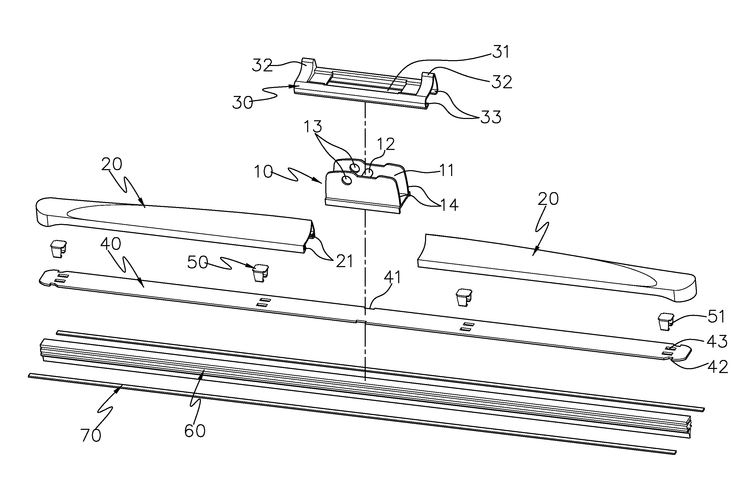
[0102]The present invention discloses a boneless wiper blade (as shown in FIGS. 4, 5 and 6), which is one preferred embodiment of the present invention. The said wiper blade consists of a pivot socket 10, two end ferrules 20, a pivot socket cover 30, a piece of spring steel sheet 40, several clutches 50, a rubber strip 60 and two spacers 70, along with a connecting device mounted on the pivot socket 10 (provided blow for details), wherein:

[0103]The said pivot socket 10 is provided with two support walls 14; inner notch 11 is formed between two support walls 14; inner notch 11 is provided with a column 12; a hole 13 is provided at the support wall 14; a concave 17 is provided at the top, and a slot 15 and slot point 16 are provide at the lower part of the pivot socket 1.

[0104]As shown in FIG. 7, and FIG. 7A-7E, a inwardly kinked groove 21 is provided at the said end fe...


PUM


Abstract

The prevent invention discloses a boneless wiper blade, which mainly consists of a pivot socket, two end ferrules, spring steel sheet and rubber strip, wherein the spring steel sheet is used to support and fix the rubber strip, and the pivot socket, on which the connecting adaptors are installed to connect with wiper arms, is mounted on the center of the spring steel sheet and the rubber strip, with end ferrules mounted at both ends of them. The upper part of the wind-pressure sheathes featuring specially curved surface is designed to prevent the wiper blade from lifting off from the surface of the windshield at highway speeds. The said spring steel sheet is so parabolically designed that the rubber strip can firmly and closely contact the various windshield glasses. Both connecting structures between the connecting adaptor and the pivot socket, and the pivot socket and the spring steel sheet and rubber strip are removable, it is same with the connecting structure between end ferrule and spring steel sheet and rubber strip. In this way, it is easy to assemble, dismount and replace them, and even facilitate use of them. The wiper blade has strong compatibility in that the pivot socket can be mounted with various kinds of connecting adaptors to be compatible with multiple wiper arm configurations.

Description

FIELD OF THE INVENTION[0001]This invention relates to a wiper blade used for the windshield glass, and more particularly, to a boneless wiper blade.DESCRIPTION OF THE RELATED ART[0002]Windshield wiper blades for cars and vehicles are mounted to remove rainwater or impurity to prevent them from obstructing drivers' sight at the time of driving. Although they are very small relative to a car or vehicle, they play vital role in them.[0003]Generally, the wiper blade is divided into bone wiper blade and boneless wiper blade. As to bone wiper blade, the wiper blade structure is connected with wiper arms through a framework. However, the wiper blade structure is stressed by the framework at multiple points, the rubber strip for the wiper blade cannot always firmly and closely contact windshield glass, resulting in poorer performance of the wiper blade. As to boneless wiper blade, it connect with the wiper arm through the connecting device, leaving no part but the connecting device at the m...

Claims


Application Information

Patent Timeline
Patent Type & Authority Patents(United States)
IPC IPC(8): B60S1/38B60S1/40
CPCB60S1/3858B60S1/3879B60S1/4003B60S1/4019B60S1/4074B60S1/4087B60S1/381B60S1/387B60S2001/4022B60S2001/4051B60S2001/4054
Inventor WU, SHENG-ZHU
Owner XIAMEN METO AUTO PARTS
Why Eureka
Try Eureka