
Firefighters tracer line apparatus

a tracer line and firefighter technology, applied in the direction of safety belts, sport apparatus, cleaning equipment, etc., can solve the problems of inability to easily locate the point of ingress, device operation limitations, and difficulty for individuals to locate easily, so as to facilitate one-handed operation and improve line handling. , the effect of significant operating benefits

Active Publication Date: 2013-04-09
AEXION INC
View PDF22 Cites 11 Cited by
  • Summary
  • Abstract
  • Description
  • Claims
  • Application Information

AI Technical Summary

Benefits of technology

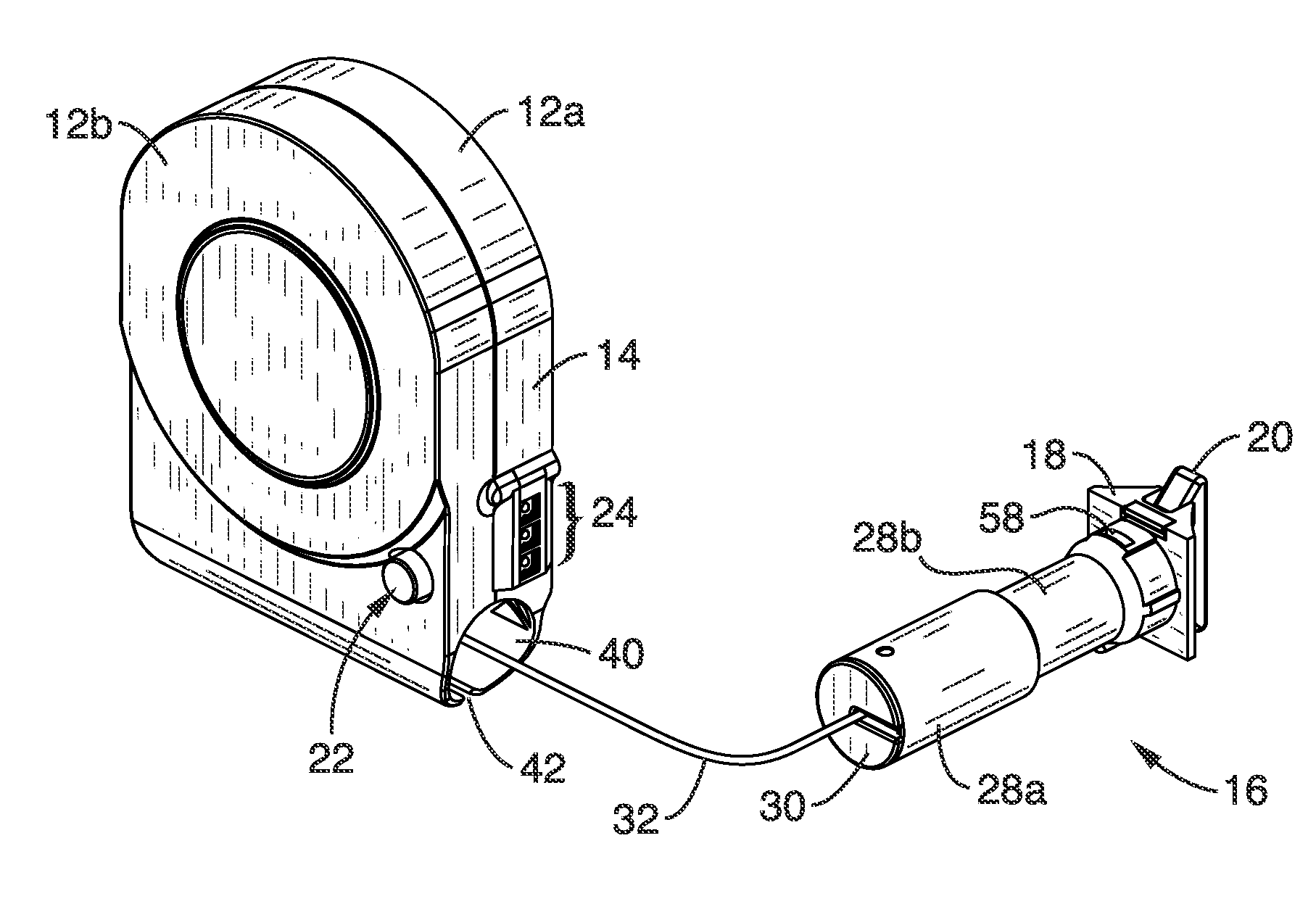
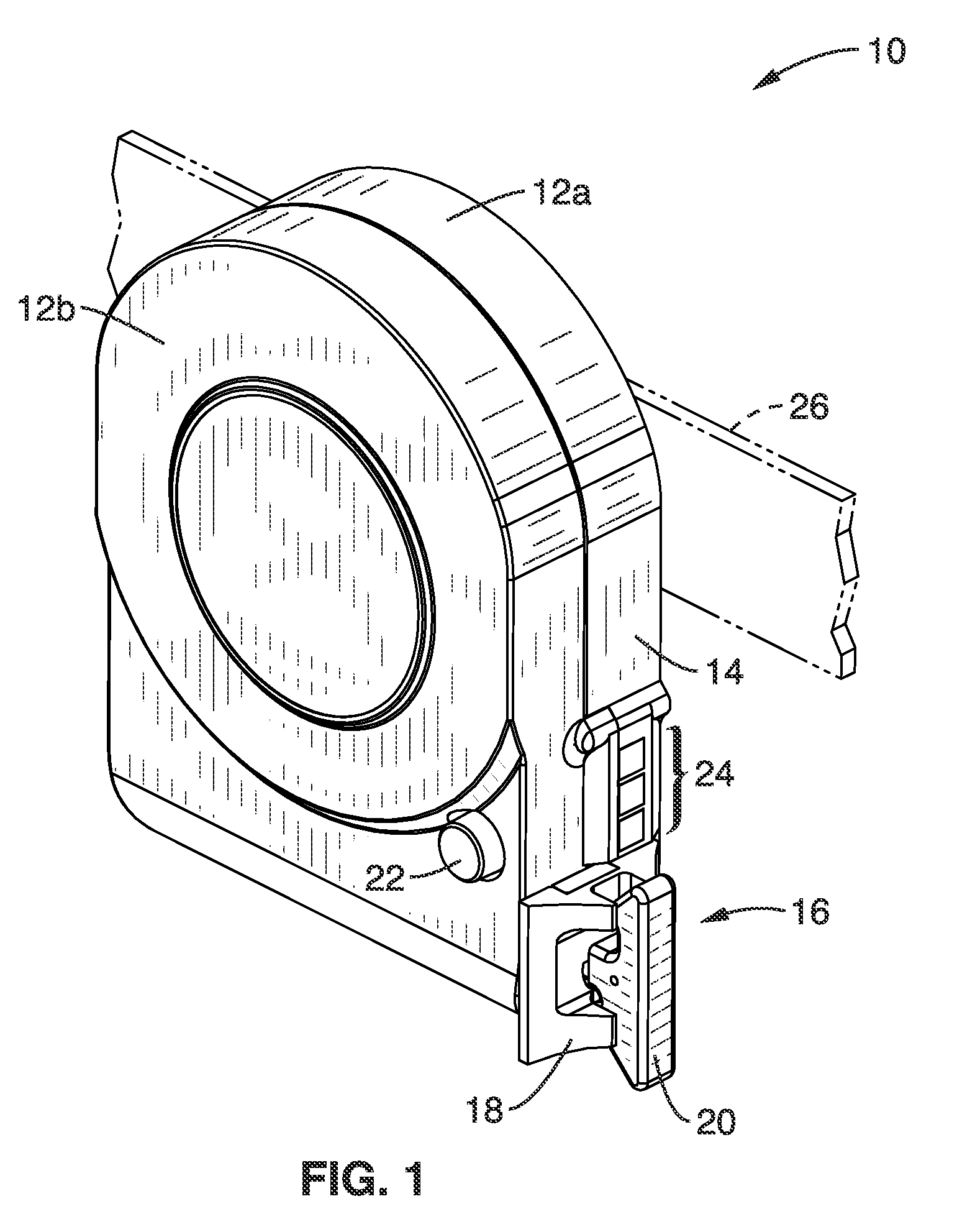
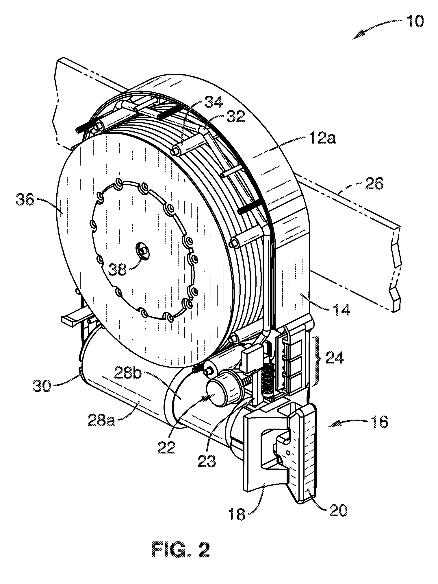
[0012]The apparatus described herein is a next generation safety line device for use by fire fighters and search and rescue personnel, and referred to by the name “Tracer Line II”. The terms “fire crews” and “fire fighters” will be used generically herein to refer without limitation to any individuals utilizing the present invention in the performance of fire fighting and rescue duties, including fire crews, fire fighters, rescue workers, Urban Search and Rescue Team (USART) members, and so forth. The safety line according to the present invention is designed to provide significant operating benefits. The new tracer-line device is a multi-functional, self-contained safety location line which facilitates one-handed operation for safe ingress and egress from a search environment, provides improved line handling, and a number of additional safety features.

Problems solved by technology

Upon attempting to egress that room, the limited visibility and conditions often make it very difficult for the individual to readily locate the point of ingress from which they entered the room.
As a result, fire fighters can be seriously injured or lose their lives attempting to locate the way back out of a room in a burning structure.
A number of problems have arisen with the use of these simple rope bag mechanisms, spawning an improved safety line solution as described by a prior patent issued to the inventor.
Although providing additional safety and convenience over conventional rope bags, these devices still had operative limitations.

Method used


Image

  • Firefighters tracer line apparatus
  • Firefighters tracer line apparatus
  • Firefighters tracer line apparatus

Examples


Embodiment Construction

[0064]Referring more specifically to the drawings, for illustrative purposes the present invention is embodied in the apparatus generally shown in FIG. 1 through FIG. 15. It will be appreciated that the apparatus may vary as to configuration and as to details of the parts, and that the method may vary as to the specific steps and sequence, without departing from the basic concepts as disclosed herein.

1. Tracer Line Structures

[0065]The Tracer Line device described herein is preferably implemented within a compact and lightweight housing so that it may be easily carried by fire crews and other emergency and rescue personnel. A multi-attach anchor head is extendable on a line from the housing for quick and secure attachment to structural building features, such as the door hinge gap (space between door and door jamb or frame), grasping a building structural element in the anchor head, or by wrapping the tracer line around an anchor point structure and securing it, to assure that the us...


PUM


Abstract

A rescue line apparatus is configured as a horizontal tether for being readily connected between a door and a portion of the door jamb or other entry location and extending a line as the user moves within the structure. The device allows the user to readily locate their way back for egressing the structure, and can be readily disengaged by the user, which activates a braking system that prevents unit “run-away”. A multi-attach anchor head couples the far end of the line to any desired structure, and has a beacon assembly which outputs a light pattern of sufficient brightness to be seen by the user when visually locating their attachment point within the structure. A multi-element visual indicator is configured for indicating line extension distance, and displaying tether line status. Many options promote safety and a fully cooperative environment.

Description

CROSS-REFERENCE TO RELATED APPLICATIONS[0001]This application claims priority from U.S. provisional application Ser. No. 61 / 210,876 filed on Mar. 24, 2009, incorporated herein by reference in its entirety.STATEMENT REGARDING FEDERALLY SPONSORED RESEARCH OR DEVELOPMENT[0002]Not ApplicableINCORPORATION-BY-REFERENCE OF MATERIAL SUBMITTED ON A COMPACT DISC[0003]Not ApplicableNOTICE OF MATERIAL SUBJECT TO COPYRIGHT PROTECTION[0004]A portion of the material in this patent document is subject to copyright protection under the copyright laws of the United States and of other countries. The owner of the copyright rights has no objection to the facsimile reproduction by anyone of the patent document or the patent disclosure, as it appears in the United States Patent and Trademark Office publicly available file or records, but otherwise reserves all copyright rights whatsoever. The copyright owner does not hereby waive any of its rights to have this patent document maintained in secrecy, inclu...

Claims


Application Information

Patent Timeline
Patent Type & Authority Patents(United States)
IPC IPC(8): A62B35/00
CPCA62B99/00A62B3/00
Inventor HERMANN, RONALD WILLIAMHUDSON, ANDREWADAIR, CARALIN
Owner AEXION INC
Learn More