Roof airbag apparatus for vehicle

a technology for airbags and roofs, which is applied in the direction of vehicle components, pedestrian/occupant safety arrangements, vehicular safety arrangments, etc., can solve the problems of airbag door hitting the windshield, increased vehicle weight, and windshield damage, and achieves the effect of small volum

Inactive Publication Date: 2013-04-09
HYUNDAI MOTOR CO LTD
View PDF14 Cites 25 Cited by
  • Summary
  • Abstract
  • Description
  • Claims
  • Application Information

AI Technical Summary

Benefits of technology

[0012]Various aspects of the present invention are directed to provide a roof airbag apparatus for a vehicle which is configured such that even though an air tube which is deployed from a roof panel of the vehicle has a comparatively small volume, it can safely protect a passenger in the event of a vehicle collision.
[0023]As described above, the present invention has the following effects.
[0024]First, an air tube which is deployed from a roof panel of the vehicle can effectively and safely protect a passenger from impact when a vehicle collision occurs.
[0025]Second, the air tube is deployed into space between a crash pad and the passenger. The air tube has a comparatively small volume. Because a small volume air tube is used, the entire weight of the vehicle is reduced, and the production cost of the air bag apparatus is reduced.

Problems solved by technology

However, in the conventional passenger seat airbag apparatus having the above-mentioned construction, when the airbag door opens to deploy the airbag cushion, the airbag door strikes the windshield.
Thereby, the windshield may be broken.
In the case where the airbag having the large capacity is used, the entire weight of the vehicle increases, and the production cost of the airbag apparatus increases.
This makes it difficult to standardize the passenger seat airbag apparatus.

Method used


Image

  • Roof airbag apparatus for vehicle
  • Roof airbag apparatus for vehicle
  • Roof airbag apparatus for vehicle

Examples


first embodiment

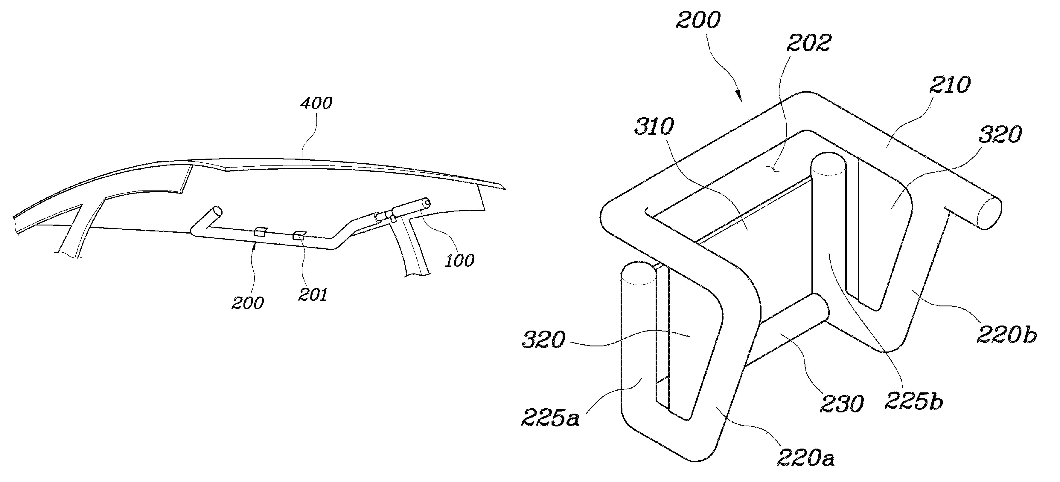
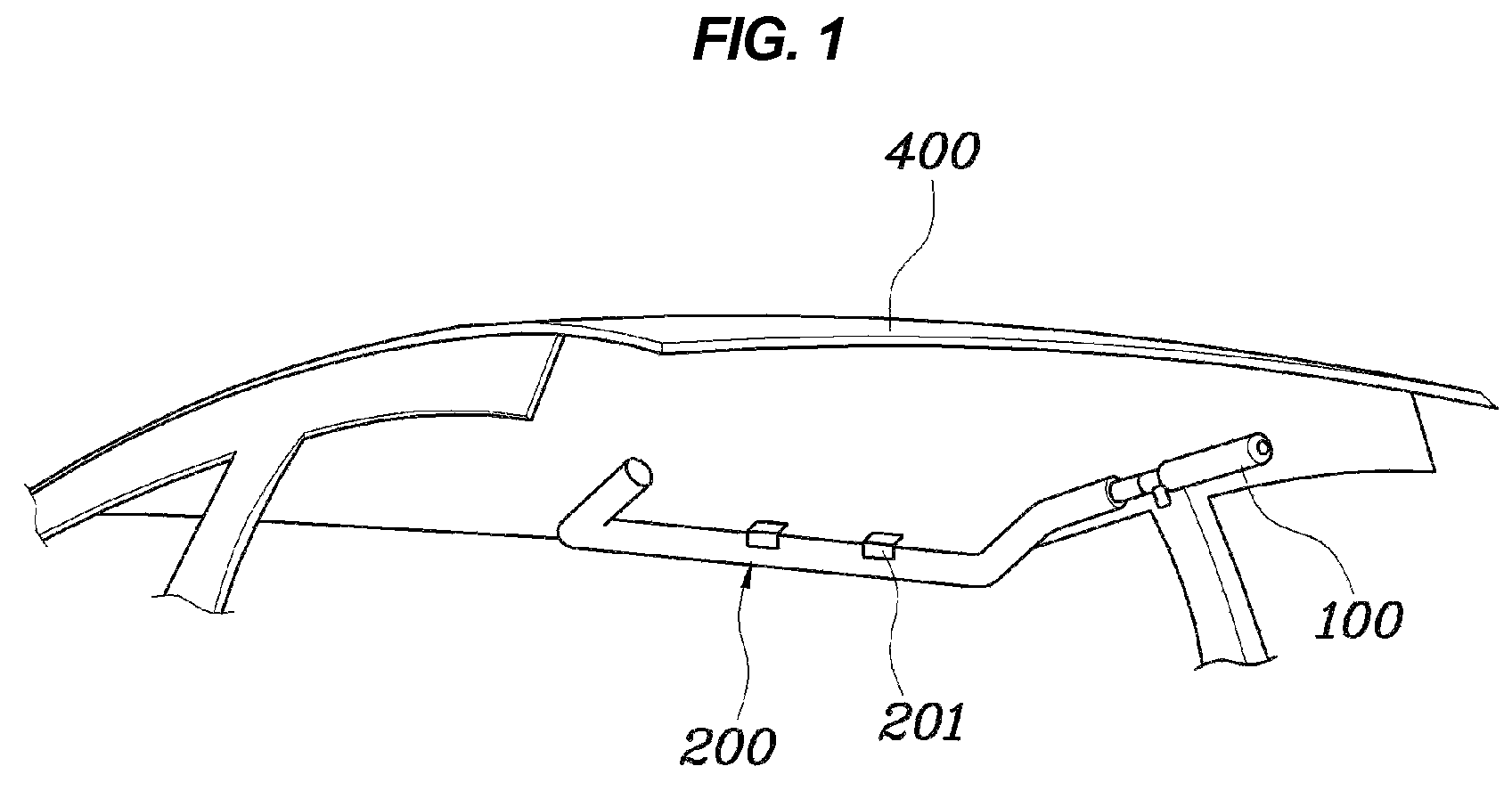
[0043]As shown in FIGS. 2 and 3, in a roof airbag apparatus according to the present invention, an air tube 200 is installed in the space defined between a roof panel 400 and a headlining and maintained in a folded state under normal conditions. When a vehicle collision occurs, the air tube 200 comes out through a tear line which is formed in the headlining and then deploys towards both sides of the passenger 500 who is sitting on a vehicle seat.

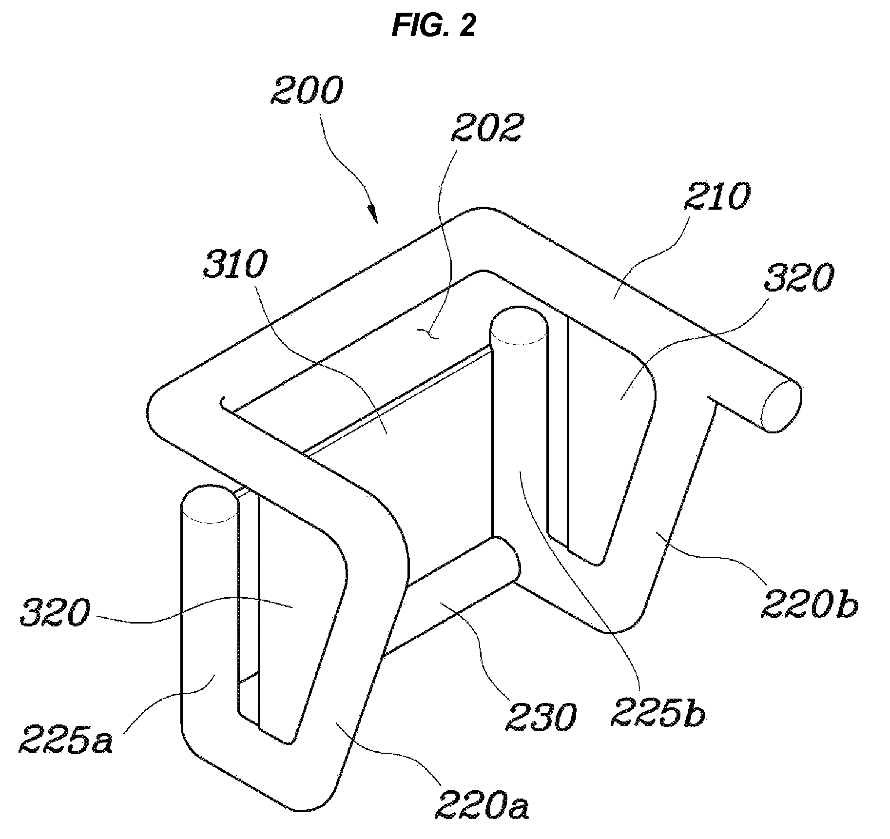
[0044]The air tube 200 includes a support tube 210, first and second bent tubes 220a and 220b, first and second front bent tubes 225a and 225b, and a connection tube 230.

[0045]The support tube 210 has a ‘U’ shape, the open portion of which is oriented towards the rear of the vehicle. The support tube 210 is fastened to the roof panel 400 by a plurality of fastening pieces 201. The reason for the ‘U’ shape of the support tube 210 is that when the air tube 200 is deployed to absorb an impact applied to the passenger 500, the ‘U’-shaped support...

second embodiment

[0054]As shown in FIG. 5, in a roof airbag apparatus according to the present invention, an air tube 200 includes a support tube 210 and first and second bent tubes 220a and 220b. The first and second front bent tubes 225a and 225b are connected to each other only by a front support panel 310. A side support panel 320 is provided in each of the first and second bent tubes 220a and 220b. A space 202 is defined between the front support panel 310 and the support tube 210.

[0055]When a vehicle collision occurs, gas is supplied from the inflator 100 into the first and second bent tubes 220a and 220b and the first and second front bent tubes 225a and 225b through the support tube 210. Then, the first and second bent tubes 220a and 220b and the first and second front bent tubes 225a and 225b are deployed from the headlining towards the front of the passenger 500. Thereby, the front support panel 310 and the side support panels 320 spread out to enclose the front and both sides of the passe...

third embodiment

[0056]As shown in FIG. 6, in a roof airbag apparatus according to the present invention, an air tube 200 includes a support tube 210, first and second bent tubes 220a and 220b, the first and second front bent tubes 225a and 225b, a connection tube 230 and a front auxiliary cushion 240. A front support panel 310 including the front auxiliary cushion 240 protrudes upwards from an upper portion of the connection tube 230. A space 202 is formed above and on opposite sides of the front support panel 310.

[0057]The front auxiliary cushion 240 is provided on the front support panel 310 and communicated with the connection tube 230 so that gas can be supplied from the connection tube 230 into the front auxiliary cushion 240. As such, because gas is supplied into the front support panel 310 through the front auxiliary cushion 240, the roof airbag apparatus of this embodiment can more safely protect the front of the passenger 500 from impact.


PUM


Abstract

A roof airbag apparatus for a vehicle, may include an inflator providing gas pressure, an air tube deploying towards sides of a passenger sitting on a seat when gas may be supplied from the inflator into the air tube, and a front support panel provided on a front end of the air tube to enclose a front portion of the passenger when the air tube may be deployed.

Description

CROSS-REFERENCE TO RELATED APPLICATIONS[0001]The present application claims priority to Korean Patent Application No. 10-2010-0112114 filed on Nov. 11, 2010, the entire contents of which is incorporated herein for purposes by this reference.BACKGROUND OF THE INVENTION[0002]1. Field of the Invention[0003]The present invention relates generally to roof airbag apparatuses for vehicles and, more particularly, to a roof airbag apparatus for a vehicle which is configured such that even though an air tube which is deployed from a roof panel of the vehicle has a comparatively small volume, it can effectively protect a passenger in the event of a vehicle collision.[0004]2. Description of Related Art[0005]Generally, airbag apparatuses protect the upper bodies of passengers in such a way that the airbag cushions are rapidly inflated by injecting air or gas into airbag cushions when vehicle collisions occur. Such airbag apparatuses are classified into a driver seat airbag apparatus which protec...

Claims


Application Information

Patent Timeline
Patent Type & Authority Patents(United States)
IPC IPC(8): B60R21/213B60R21/231
CPCB60R21/231B60R21/213B60R2021/23386
Inventor LEE, CHANG HYUNCHOI, HYEONG HOJO, SANG MINLEE, UN KOO
Owner HYUNDAI MOTOR CO LTD
Why Eureka
Try Eureka