Battery storage structure for acoustic equipment

a technology of acoustic equipment and storage structure, which is applied in the direction of electrical equipment, cell components, cell component details, etc., can solve the problems of battery storage section vibrating considerably, resonance resonance causing harsh noise to the ear, and consequent vibration of resonan

Active Publication Date: 2013-04-09
ROLAND CORP
View PDF4 Cites 0 Cited by
  • Summary
  • Abstract
  • Description
  • Claims
  • Application Information

AI Technical Summary

Benefits of technology

[0004]However, in the conventional radio receiver described above, the speaker is stored inside the housing, so that when musical sound outputted from the speaker reaches a certain frequency, the housing is induced to resonate. In particular, in a device such as an amplifier equipped with a speaker, musical sounds outputted from the speaker are relatively loud, and therefore vibrations resulting from resonance are consequently large. Accordingly, a problem occurs in that the noise caused by resonance is harsh to a person's ear when the person listens to the musical sounds from the speaker. Furthermore, the resonance of the housing also causes batteries stored in the battery storage section to vibrate considerably. This results in problems such as contact failures between batteries and terminals that electrically connect circuits inside the housing, short circuits, battery leakages, and the like.
[0008]To achieve these and other advantages and in accordance with the purpose of the present invention, as embodied and broadly described, the present invention is embodied in a battery storage structure for acoustic equipment having a housing and a battery-driven speaker disposed on the housing, the battery storage structure for storing a battery in the housing and comprising a case storage section disposed in the housing and having an open surface, a battery case having an open surface and stored within the case storage section, wherein the open surface of the battery case is oriented in the same direction as the open surface of the case storage section, and at least one connection section connecting the battery case and the case storage section, wherein a predetermined gap is formed between an inner bottom surface of the case storage section and an outer bottom surface of the battery case, and between an inner side surface of the case storage section and an outer side surface of the battery case.
[0002]The present invention relates to a battery storage structure for acoustic equipment, and in particular to battery storage structures in acoustic equipment that can reduce noise caused by vibration, as well as prevent contact failures between batteries and terminals, short-circuits and leakages in batteries.
[0002]The present invention relates to a battery storage structure for acoustic equipment, and in particular to battery storage structures in acoustic equipment that can reduce noise caused by vibration, as well as prevent contact failures between batteries and terminals, short-circuits and leakages in batteries.

Problems solved by technology

In particular, in a device such as an amplifier equipped with a speaker, musical sounds outputted from the speaker are relatively loud, and therefore vibrations resulting from resonance are consequently large.
Accordingly, a problem occurs in that the noise caused by resonance is harsh to a person's ear when the person listens to the musical sounds from the speaker.
Furthermore, the resonance of the housing also causes batteries stored in the battery storage section to vibrate considerably.
This results in problems such as contact failures between batteries and terminals that electrically connect circuits inside the housing, short circuits, battery leakages, and the like.

Method used


Image

  • Battery storage structure for acoustic equipment
  • Battery storage structure for acoustic equipment
  • Battery storage structure for acoustic equipment

Examples


Embodiment Construction

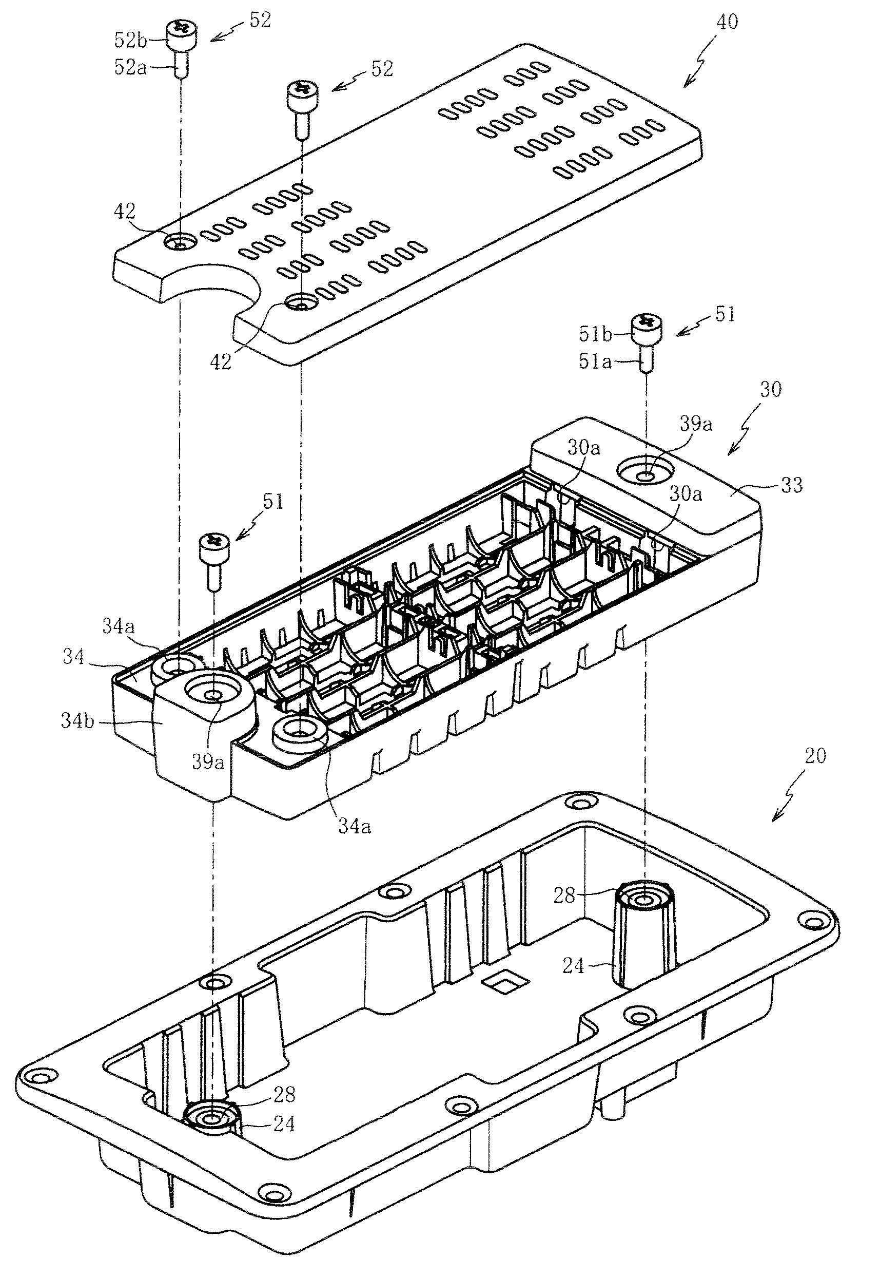
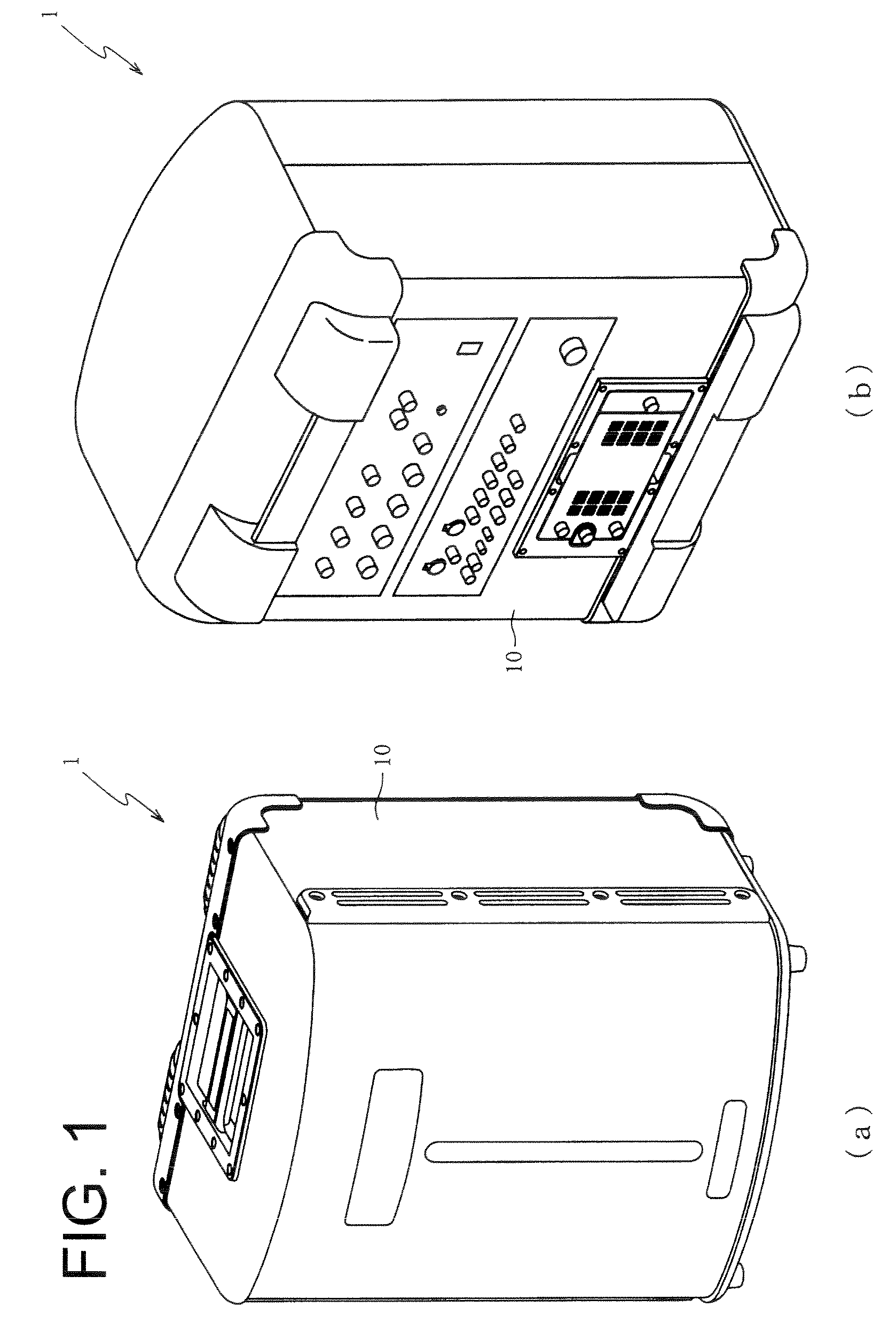
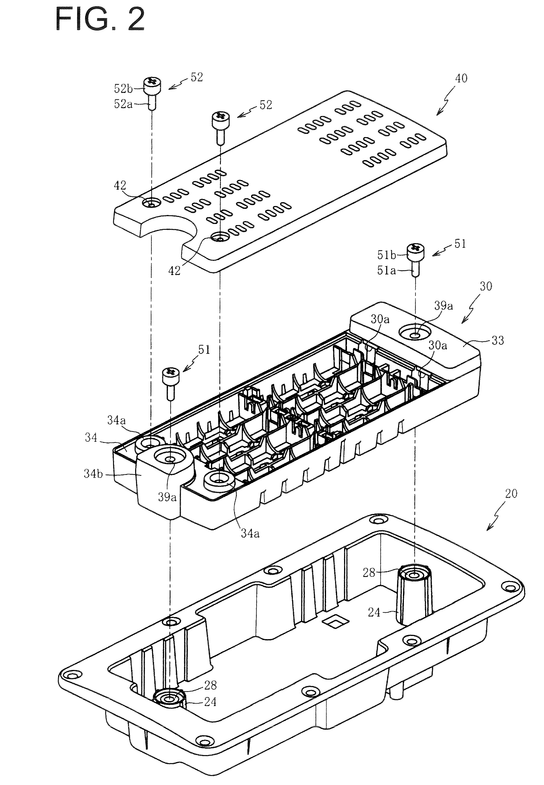
[0031]The present invention relates to a battery storage structure for acoustic equipment. Below, preferred embodiments of the present invention will be described with reference to the accompanying drawings. First, a battery storage structure of an amplifier with a built-in speaker 1 according to one embodiment of the invention will be described with reference to FIGS. 1 and 2. FIG. 1(a) is a front perspective view of an amplifier with a built-in speaker 1 according to one embodiment of the invention. FIG. 1(b) is a rear perspective view of an amplifier with a built-in speaker 1 according to one embodiment of the invention. FIG. 2 is an exploded perspective view of a battery storage structure of an amplifier with a built-in speaker 1. It is noted that, in FIG. 2, illustration of storage terminal plates 26a, 26b (as shown in FIG. 3) and case terminal plates 36 (as shown in FIG. 5) is omitted.

[0032]As shown in FIGS. 1(a) and 1(b), the amplifier with a built-in speaker 1 is acoustic eq...


PUM

PropertyMeasurementUnit
voltageaaaaaaaaaa
voltageaaaaaaaaaa
voltageaaaaaaaaaa

Abstract

The present invention relates to a battery storage structure for acoustic equipment having a housing and a battery-driven speaker disposed on the housing, the battery storage structure for storing a battery in the housing. A case storage section is disposed in the housing and has an open surface. A battery case has an open surface and is stored within the case storage section, wherein the open surface of the battery case is oriented in the same direction as the open surface of the case storage section. At least one connection section connects the battery case and the case storage section, wherein a predetermined gap is formed between an inner bottom surface of the case storage section and an outer bottom surface of the battery case, and between an inner side surface of the case storage section and an outer side surface of the battery case.

Description

CROSS-REFERENCE TO RELATED APPLICATIONS[0001]Pursuant to 35 U.S.C. §119(a), this application claims the benefit of earlier filing date and right of priority to Japanese Application No. 2009-222158, filed on Sep. 28, 2009, the contents of which are hereby incorporated by reference herein in their entirety.FIELD OF THE INVENTION[0002]The present invention relates to a battery storage structure for acoustic equipment, and in particular to battery storage structures in acoustic equipment that can reduce noise caused by vibration, as well as prevent contact failures between batteries and terminals, short-circuits and leakages in batteries.BACKGROUND OF THE INVENTION[0003]Numerous acoustic equipment, acoustic equipment equipped with a speaker and the like have been conventionally developed. For example, there previously exists a conventional radio receiver having a speaker stored inside a housing, and a battery storage section for storing batteries formed in a rear cabinet that constitute...

Claims


Application Information

Patent Timeline
Patent Type & Authority Patents(United States)
IPC IPC(8): H01M2/00H01M2/02H01M50/227H01M50/278
CPCH01M2/1022H04R1/02Y02E60/10H01M50/278H01M50/227
Inventor NAGAOKA, YASUNORIMURAMATSU, HIROFUMI
Owner ROLAND CORP
Why Eureka
Try Eureka