Contaminant removal method for fractionating columns

a technology of fractionation column and contaminant removal method, which is applied in the direction of hydrocarbon oil treatment, distillation separation, refining by water treatment, etc., can solve the problems of reducing the performance of the reboiler, mechanical failure of the reboiler tube, corrosion of the internal components of the tower and the reboiler,

Active Publication Date: 2019-10-03
GAS LIQUIDS ENG LTD
View PDF3 Cites 1 Cited by
  • Summary
  • Abstract
  • Description
  • Claims
  • Application Information

AI Technical Summary

Benefits of technology

[0015]The addition of the secondary separator as stated within the circuit has been found to have a significant result in contaminant management within the circuit as will be evident from the data to be presented herein. This is further augmented with the recognition of the effect of the temperature and pressure parameters to prevent boiling. Conveniently, the secondary separator addition is envisioned for retrofit applications in existing prior art circuits.

Problems solved by technology

Over time, this build up causes reduced performance of the reboiler, and will eventually cause failure due to fouling, or tube rupture due to the volume of solid contaminant causing mechanical failure of the reboiler tubes.
The water / contaminant mixture in the hydrocarbon liquid stream can also cause corrosion to the internal components of the tower and the reboiler if constantly recycled throughout the system.
In light of the fact that processing of unconventional oil and natural gas reserves is a new development, mitigating solutions have not been proposed with any real result.
There is significant downtime for cleaning with the disassembly, reassembly, and ramp up for the apparatus in the fractionating circuit inter alia.
Economics in terms of production costs are commensurately unappealing.
Accordingly, processing in a logistically and economically effective manner is complex and requires elegant management of process parameters.

Method used


Image

  • Contaminant removal method for fractionating  columns
  • Contaminant removal method for fractionating  columns
  • Contaminant removal method for fractionating  columns

Examples


Embodiment Construction

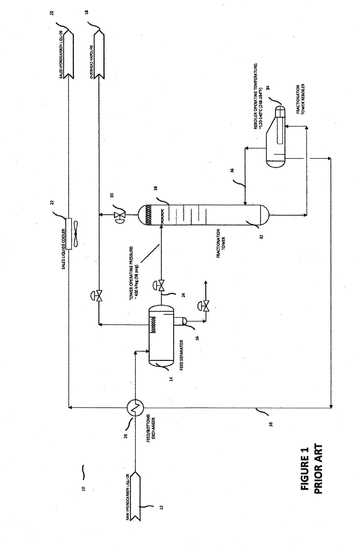
[0033]Referring now to the Figures, FIG. 1 is a process flow diagram of a prior art fractionating circuit, generally denoted by numeral 10. In the circuit, the feed stream 12 composed of the raw hydrocarbons enters the feed / bottom exchanger 26 and subsequently into the feed separator 14 for initial processing.

[0034]Separated contaminants exit at 16 with overhead vapours 18 and saleable hydrocarbons 20 separated as well.

[0035]Further processing of the secondary feed stream 24 extends through to the fractionating tower 28. Overhead vapours are removed from fractionating tower 28 at 30. In the prior art example, the fractionating tower is typically operated at pressures between 40-70 psig.

[0036]Hydrocarbon material exiting the fractionating tower 28 at fractionating tower bottom 32 is circulated through reboiler 34 which typically operates at between 120° C. and 140° C. A recirculation loop 36 is provided as well as a removal loop 38 for saleable hydrocarbon removal.

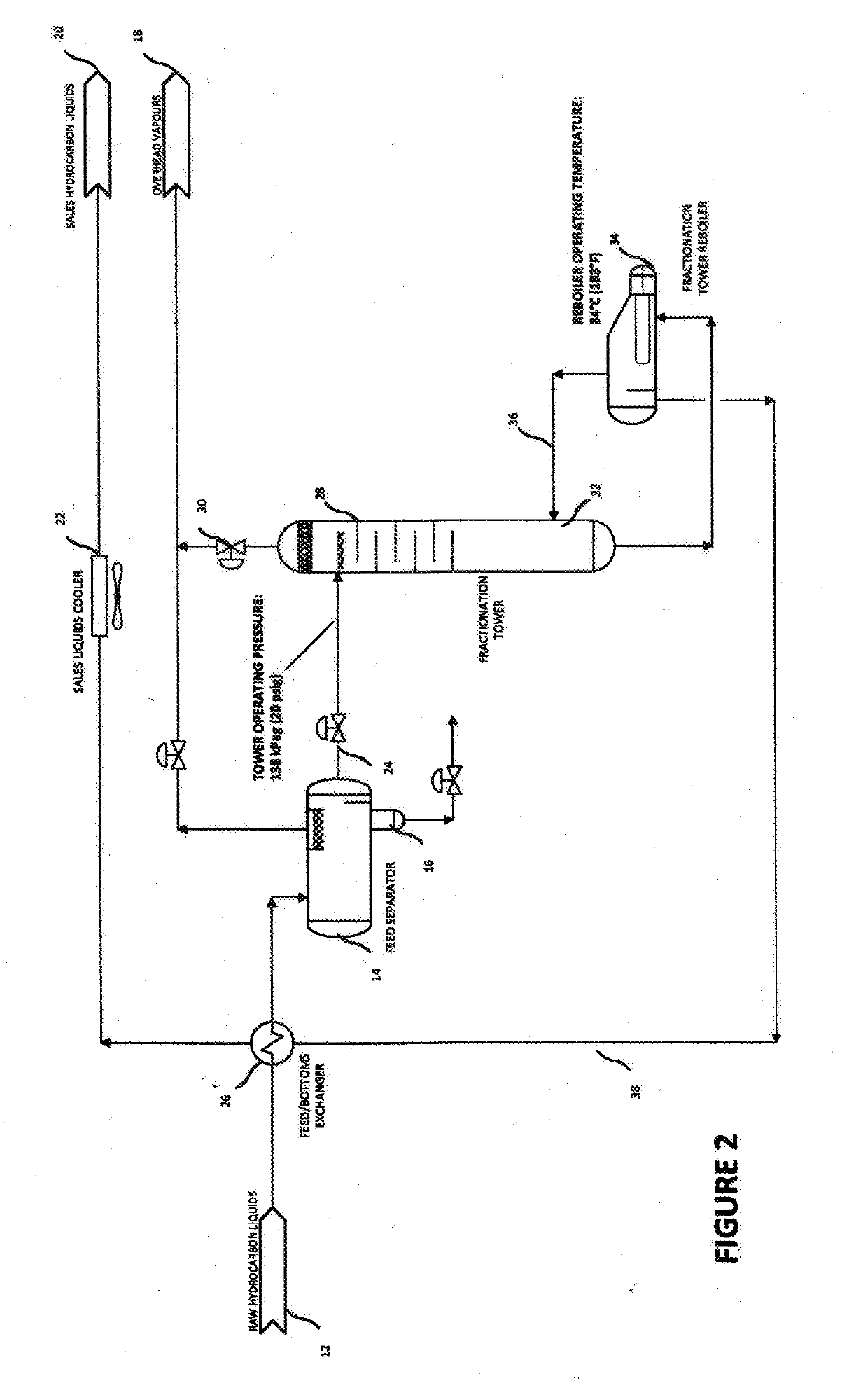
[0037]Turning to FI...


PUM

PropertyMeasurementUnit
pressuresaaaaaaaaaa
pressureaaaaaaaaaa
temperatureaaaaaaaaaa

Abstract

Methods for removing water and/or dissolved and solid contaminants from a liquid hydrocarbon such as condensate flowing through a fractionating column are disclosed. Pressure within the column and temperature at which the reboiler operates are observed to prevent boiling of the contaminated hydrocarbon thus obviating contaminant deposition on heated surfaces. Further methods directed to column operation and anti-fouling procedures augment the core method. Apparatus to effect the methods is also provided.

Description

FIELD OF THE INVENTION[0001]The present invention relates to contaminant removal from raw hydrocarbon liquids and more particularly, the present invention relates to a contaminant removal method and apparatus using a fractionating platform.BACKGROUND OF THE INVENTION[0002]Raw hydrocarbon liquids entering a facility, such as condensate, often carry entrained water and dissolved and / or free solid contaminants along with them as a result of the extraction process and ground conditions found in the area of production. In order to turn these raw liquids into a sales product at a facility, these raw hydrocarbon liquids must be sent through a fractionating column in order to strip away the light hydrocarbon ends.[0003]The reboiler temperatures required to process these raw hydrocarbon liquids cause any water carried over from the feed separator at the inlet of the system to boil off, which deposits any dissolved salts contained in the water on the outside of the tubes located inside the re...

Claims


Application Information

Patent Timeline
Patent Type & Authority Applications(United States)
IPC IPC(8): C10G31/08C10G75/04B01D3/32B01D3/34
CPCB01D3/34C10G2300/805C10G75/04C10G31/08C10G2300/4075B01D3/322B01D1/28B01D3/32
Inventor MARSHALL, DEREK B.MACKENZIE, STUART D.MACKENZIE, KELLY R.
Owner GAS LIQUIDS ENG LTD
Why Eureka
Try Eureka