Method of increasing the safety of a power plant, and a power plant suitable for implementing the method

a technology of safety and power plant, applied in the direction of hot gas positive displacement engine plants, gear lubrication/cooling, engine fuctions, etc., can solve the problems of prolonging the duration and giving rise to extra power, and achieve the effect of increasing the safety of a power plant and thus the safety available to an aircraft, and increasing the weight of the power plan

Active Publication Date: 2015-12-08
EUROCOPTER
View PDF19 Cites 0 Cited by
  • Summary
  • Abstract
  • Description
  • Claims
  • Application Information

AI Technical Summary

Benefits of technology

[0033]An object of the present invention is thus to propose a method enabling the safety of a power plant to be increased and thus the safety available to an aircraft as a result of its power plant, while avoiding a large resulting increase in the weight of the power plant.
[0034]The invention provides a method of increasing the safety of a power plant provided with at least one heat engine and a gearbox, the heat engine driving the gearbox, the gearbox having a main and / or emergency lubrication system implemented using an aqueous medium including water stored in a reserve, which method is remarkable in particular in that during said method a fluid is injected into the heat engine to increase the power developed by the heat engine without increasing the temperature of a member of the engine, or to decrease the temperature of said member without modifying the power developed by the heat engine, the fluid being taken from said reserve.

Problems solved by technology

The combination particularly characterizing this method has the result of giving rise to extra power or of prolonging the duration for which a particular rating may be used, for example.

Method used


Image

  • Method of increasing the safety of a power plant, and a power plant suitable for implementing the method
  • Method of increasing the safety of a power plant, and a power plant suitable for implementing the method
  • Method of increasing the safety of a power plant, and a power plant suitable for implementing the method

Examples


first embodiment

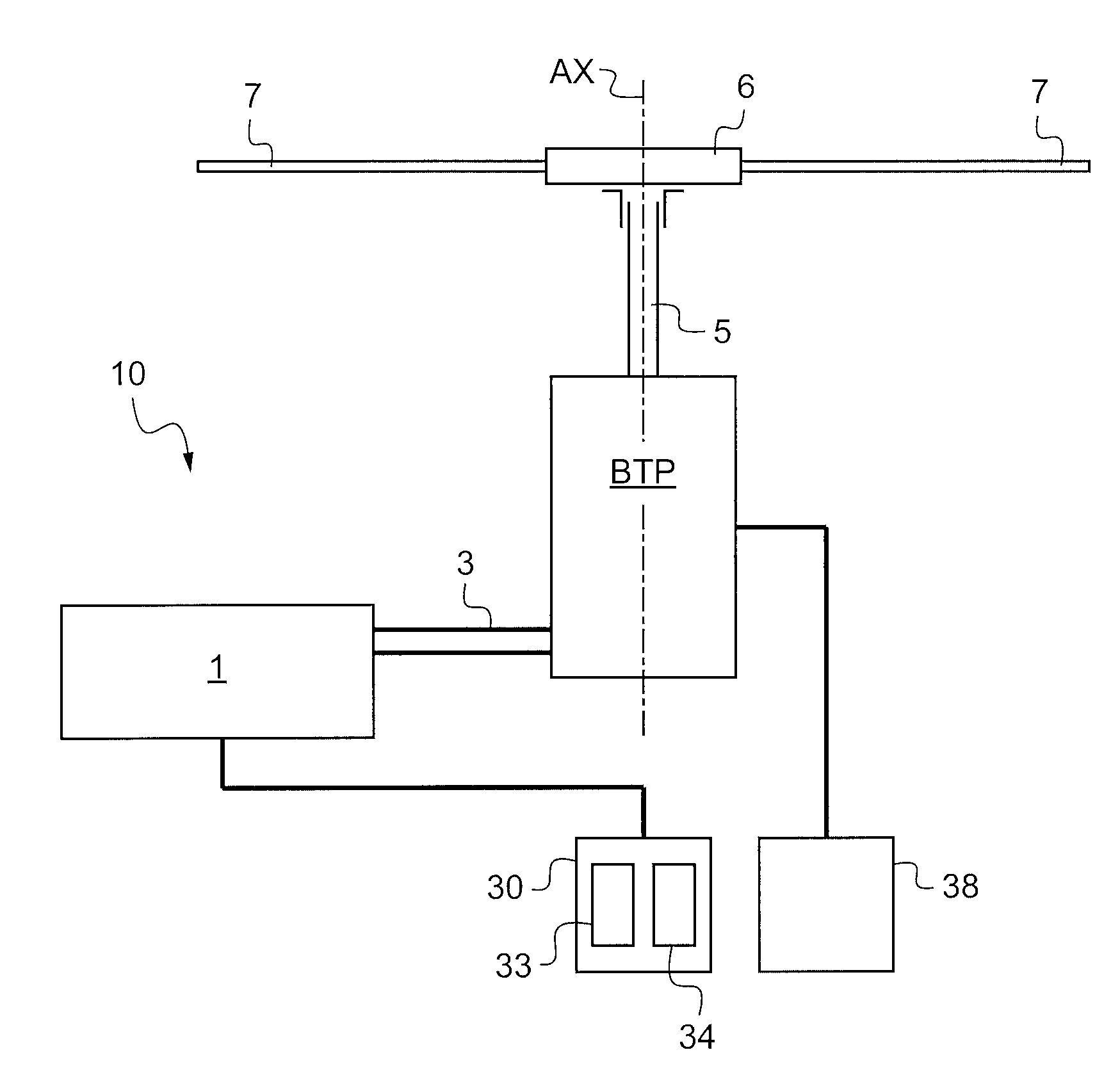
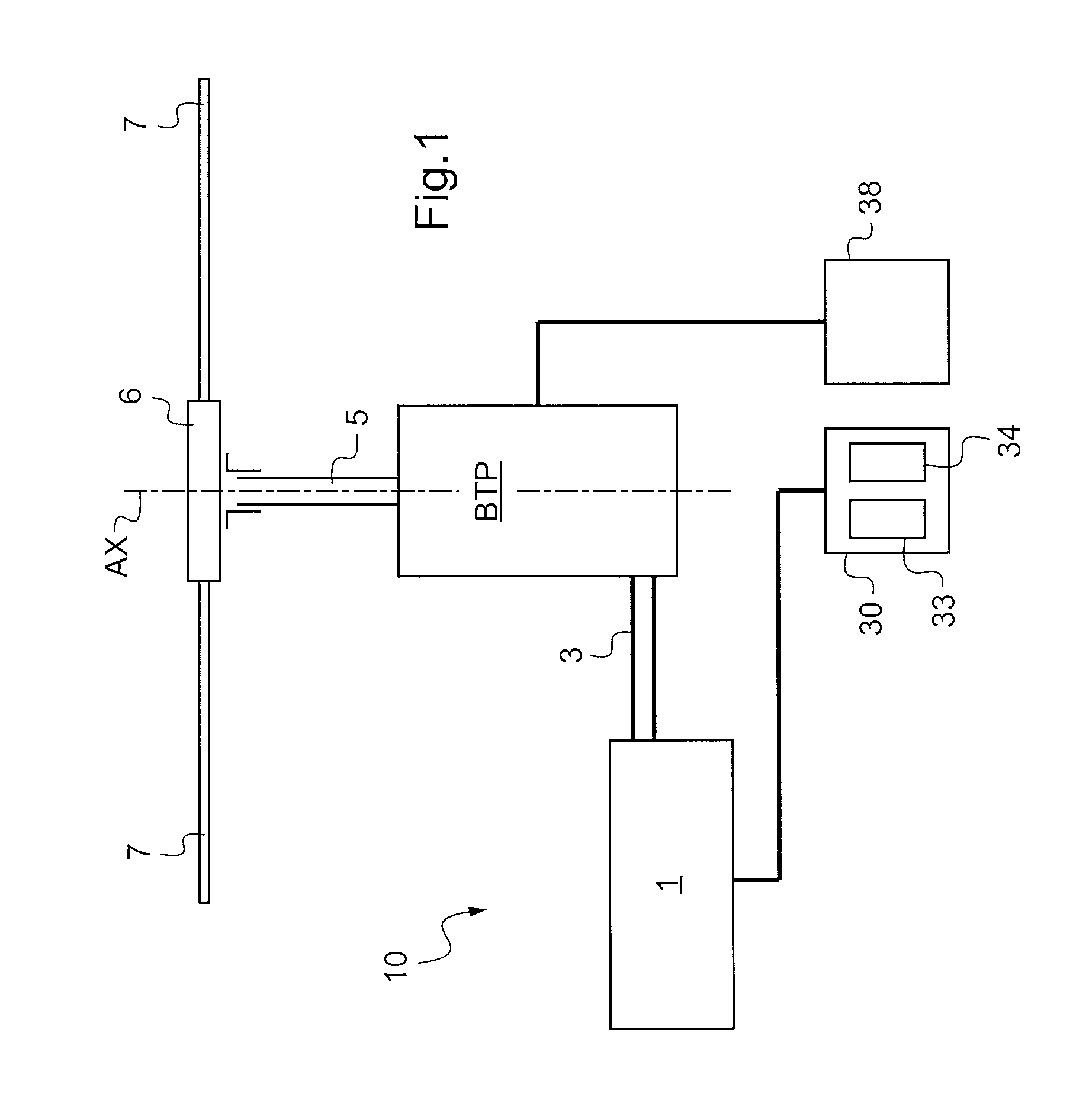
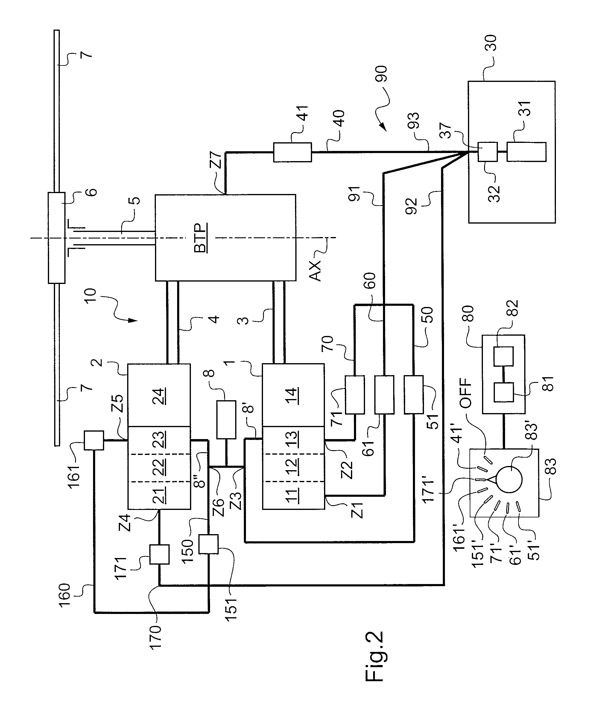
[0113]FIG. 2 shows a first embodiment provided with a reserve having one bottle, this embodiment being an embodiment that is preferred by virtue of its simplicity.

[0114]The power plant shown comprises first and second heat engines 1, 2 of the turbine engine type. These first and second heat engines 1, 2 are fed with fuel from a fuel tank 8 via respective first and second fuel feed pipes 8′ and 8″.

[0115]Thus, the first heat engine 1 is provided with a first gas generator comprising in succession a first air inlet 11, a first compressor 12, with a first combustion chamber 13, a first turbine connected to the first compressor 12 optionally being located at the outlet from the first combustion chamber 13. A first free turbine stage 14 is located downstream from the first gas generator, i.e. after the first combustion chamber 13 or the first turbine, as appropriate.

[0116]Similarly, the second heat engine 2 is provided with a second gas generator comprising in succession a second air inle...

second embodiment

[0137]With reference to FIG. 3, in a second embodiment, the reserve 30 includes a plurality of bottles, each provided with a pump leading to a mixer 37.

[0138]For example, the reserve 30 includes a first bottle 33 of pure water associated with a first pump 35, and a second bottle33 associated with a second pump 36 and containing an intermediate solution comprising either antifreeze or a third mixture of at least an antifreeze and a lubricant.

[0139]Thus, when it is necessary to feed fluid to a heat engine, the processor 81 requests the mixer 37 to block the liquid coming from the second bottle. In contrast, when it is necessary to feed fluid to the gearbox, the processor requests the mixer 37 to mix the pure water of the first bottle 33 to the intermediate solution of the second bottle 34.

[0140]It should be observed that the control member 80 may be a dedicated control member, or that it may be incorporated in existing means, e.g. the member for regulating the heat engines 1 and 2.

[01...


PUM


Abstract

The present invention relates to a method of increasing the safety of a power plant (10) provided with at least one heat engine (1, 2) and a gearbox (BTP), said engine (1, 2) driving said gearbox (BTP), said gearbox (BTP) having a lubrication system implemented using an aqueous medium stored in a reserve (30), in which method a fluid comprising water is injected into said heat engine (1, 2) to increase the power developed by the heat engine (1, 2) without increasing the temperature of a member of the heat engine (1, 2), or to decrease said temperature without modifying the power developed by the engine (1, 2), said fluid being taken from said reserve (30).

Description

CROSS-REFERENCE TO RELATED APPLICATIONS[0001]This application claims the benefit of FR 09 06012 filed on Dec. 11, 2009. The disclosure of which is incorporated in its entirety by reference hereinFIELD OF THE INVENTION[0002]The present invention relates to a method of increasing the safety of a power plant, and to a power plant suitable for implementing the method.[0003]More particularly, the invention relates to a power plant for a rotorcraft, and in particular for a helicopter. The technical field of the invention is thus the technical field of power plants, in particular for aircraft of the rotorcraft type.BACKGROUND OF THE INVENTION[0004]A rotorcraft has a power plant for setting its rotary wing into rotation. The power plant is provided with one or more heat engines for driving the gearing of a power transmission gearbox, referred to as the main gearbox in a helicopter, said gearbox then driving the rotary wing in rotation.[0005]The gearbox includes mechanical moving elements, s...

Claims


Application Information

Patent Timeline
Patent Type & Authority Patents(United States)
IPC IPC(8): F02C3/30F01D15/12F16H57/04
CPCF02C3/305F01D15/12F05D2220/329F05D2260/4031F16H57/045F01D25/18F01M11/02F05D2260/98F01D25/22
Inventor VIALLE, MICHELCORPRON, ALBANDYRLA, FREDERIC
Owner EUROCOPTER
Why Eureka
Try Eureka