
Optical network in-band control plane signaling, virtualized channels, and tandem connection monitoring systems and methods

a technology of in-band control plane and monitoring system, applied in the field of optical networks, can solve the problems of limiting the flexibility of the control plane, increasing the restoration time and cost of the network, and not being able to enable in-band control plane enabled links over submarine links or tunneling through other bandwidth provider networks

Active Publication Date: 2013-04-09
CIENA
View PDF33 Cites 16 Cited by
  • Summary
  • Abstract
  • Description
  • Claims
  • Application Information

AI Technical Summary

Benefits of technology

This solution enables flexible control plane operations across submarine networks and network provider links, reduces the need for out-of-band control planes, maximizes bandwidth usage, and allows for efficient end-to-end monitoring and restoration, thereby reducing costs and improving network flexibility and reliability.

Problems solved by technology

Disadvantageously, in-band control plane enabled links are not possible over submarine links or tunneling through other bandwidth provider networks.
Signaling for these links requires an out-of-band control plane network limiting flexibility of the control plane and greatly increasing restoration times and cost of the network.
Additionally, the deployment of heterogeneous payload control plane-enabled links across submarine links or tunneling through network provider networks with control plane un-aware intermediate line terminating equipment (LTE) network elements has not been possible.
In the same way, OTN cross-connections at intermediate network elements can limit the available bandwidth.
This lack of flexibility leads to limited control plane functionality and added cost to the user.
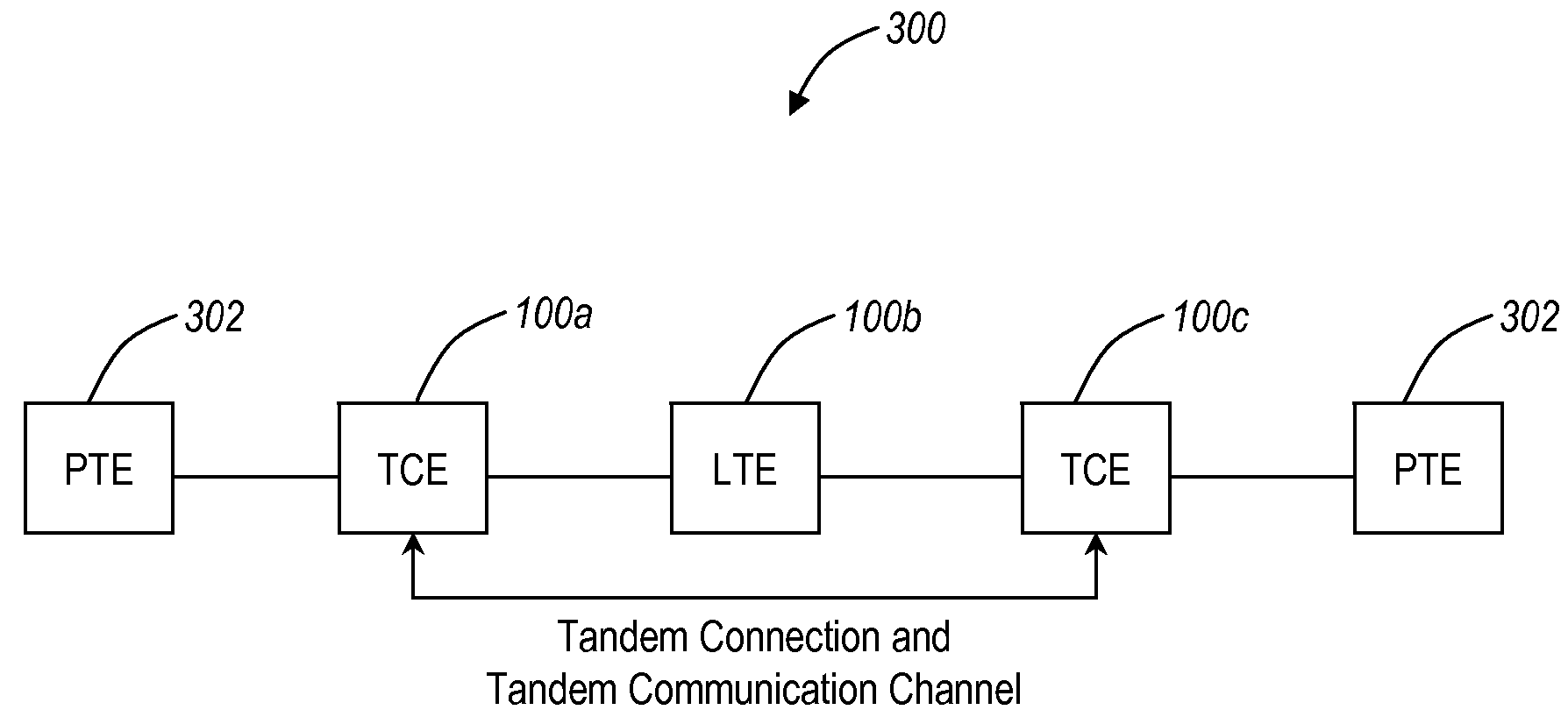
Disadvantageously with respect to tunneling through other bandwidth provider networks, only a single operator connected to each of the networks or domains may monitor each path.

Method used


Image

  • Optical network in-band control plane signaling, virtualized channels, and tandem connection monitoring systems and methods
  • Optical network in-band control plane signaling, virtualized channels, and tandem connection monitoring systems and methods
  • Optical network in-band control plane signaling, virtualized channels, and tandem connection monitoring systems and methods

Examples


Embodiment Construction

[0020]In various exemplary embodiments, the present invention relates to improvements with respect to in-band control plane signaling, virtualized channels, and tandem connection monitoring in optical networks utilizing Synchronous Optical Network (SONET), Synchronous Digital Hierarchy (SDH), Optical Transport Network (OTN), and the like. Advantageously, the Tandem Connection and Tandem Communication Channel allows the deployment of control plane links across submarine networks and through network provider links with line terminating equipment (LTE) network elements. The use of the Tandem Connection monitoring of the Control Plane line greatly increases the control plane restoration times and eliminates the need for an expensive out-of-band control plane network. The use of virtual channels allows the deployment of heterogeneous concatenation control plane links across submarine networks and through network provider links with line terminating equipment (LTE) network elements. These...


PUM


Abstract

The present disclosure provides improvements with respect to in-band control plane signaling, virtualized channels, and tandem connection monitoring in optical networks utilizing Synchronous Optical Network (SONET), Synchronous Digital Hierarchy (SDH), Optical Transport Network (OTN), and the like. In an exemplary embodiment, the present disclosure includes an optical network operating a control plane with in-band signaling utilizing SONET / SDH path level overhead. In another exemplary embodiment, the present disclosure includes an optical network operating virtualized SONET / SDH or OTN channels with manually cross-connections at intermediate line terminating elements. In yet another exemplary embodiment, the present disclosure includes a tandem connection monitoring selection method across multiple operator domains.

Description

FIELD OF THE INVENTION[0001]The present invention relates generally to optical network. More particularly, the present invention relates to improvements with respect to in-band control plane signaling, virtualized channels, and tandem connection monitoring in optical networks utilizing Synchronous Optical Network (SONET), Synchronous Digital Hierarchy (SDH), Optical Transport Network (OTN), and the like.BACKGROUND OF THE INVENTION[0002]Optical networks using SONET, SDH, OTN, and the like are being deployed with corresponding control planes for control thereof. For example, the control plane may include Optical Signaling and Routing Protocol (OSRP), Automatically Switched Optical Networks—ITU-T Recommendation G.8080: Architecture for the Automatically Switched Optical Network (ASON) 2001, Generalized Multi-Protocol Label Switching Architecture (G-MPLS) IETF RFC 3945, 2004, and the like. Using SONET, SDH, OTN, etc., the control planes may utilize either in-band signaling (e.g., via ov...

Claims


Application Information

Patent Timeline
Patent Type & Authority Patents(United States)
IPC IPC(8): H04B10/00
CPCH04J3/1611H04J3/1652H04J2203/0051H04J2203/0066
Inventor MOYNIHAN, JEFFREY SCOTTKARTAWIRA, IWANSMITH, ALEXANDER A.MADRAHALLI, VAGISHMALLI, KUMARESHSARAVANAN, PURUSHOTHAMAN
Owner CIENA
Learn More