
Method and apparatus adapted to transmit data

a technology of data transmission and transmission method, applied in the field of data transmission, to achieve the effect of high data ra

Active Publication Date: 2013-04-09
SATO HLDG CORP
View PDF42 Cites 2 Cited by
  • Summary
  • Abstract
  • Description
  • Claims
  • Application Information

AI Technical Summary

Benefits of technology

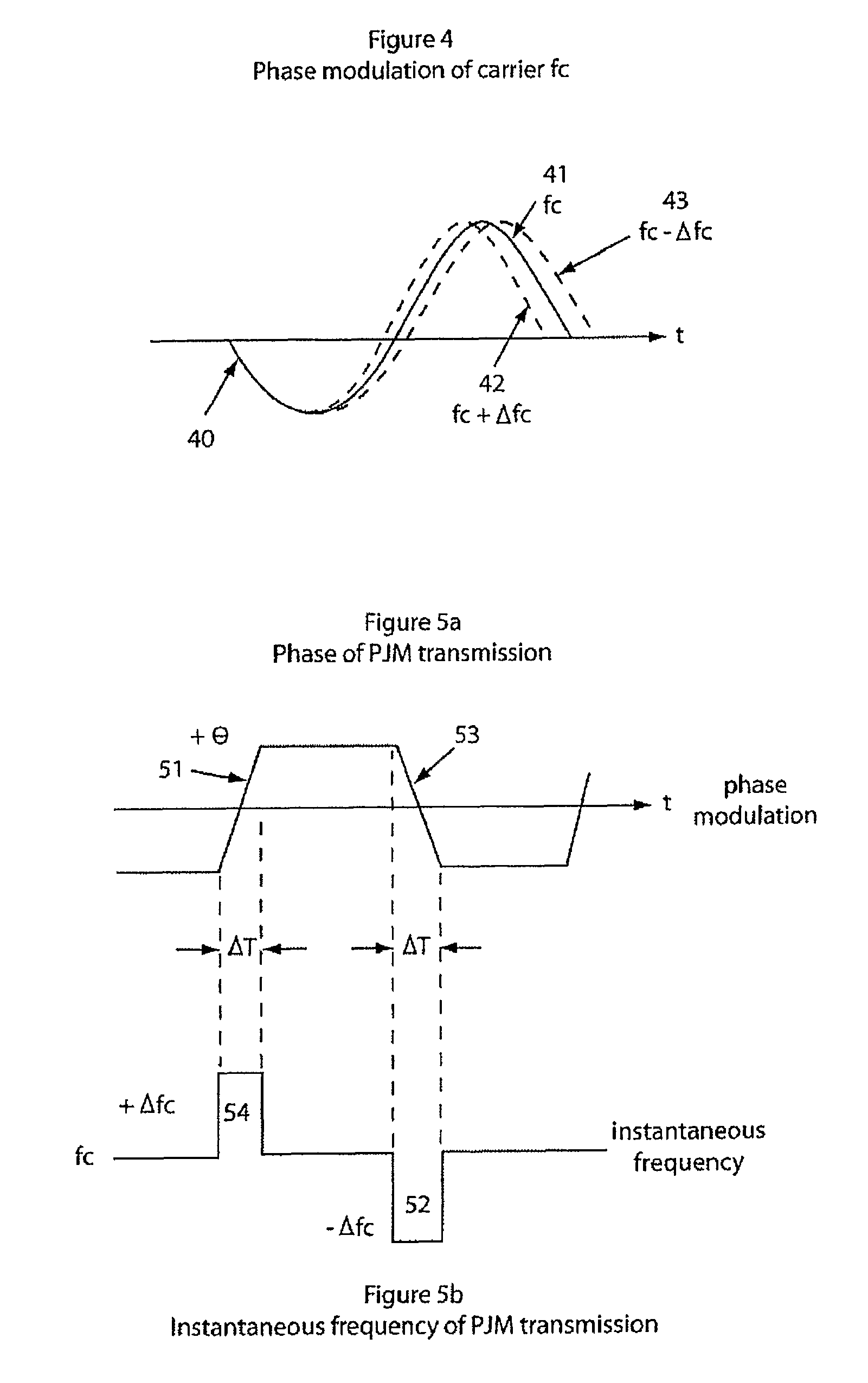
[0039]The present invention further provides a method that improves Phase Jitter Modulation (PJM) which is a very low deviation phase modulation method ideally suited to RFID. The advantages of PJM are that the excitation field amplitude is constant and the PJM bandwidth is no wider than the original data bandwidth. A full description of PJM is provided in PCT / AU98 / 01077 (which is incorporated herein by reference). In order to achieve the full benefit of PJM the transmitted PJM signal should have relatively fast phase transition rates. Fast phase transitions can not pass through high Q narrow band antenna circuits. To pass fast phase transitions a wideband antenna response is required.
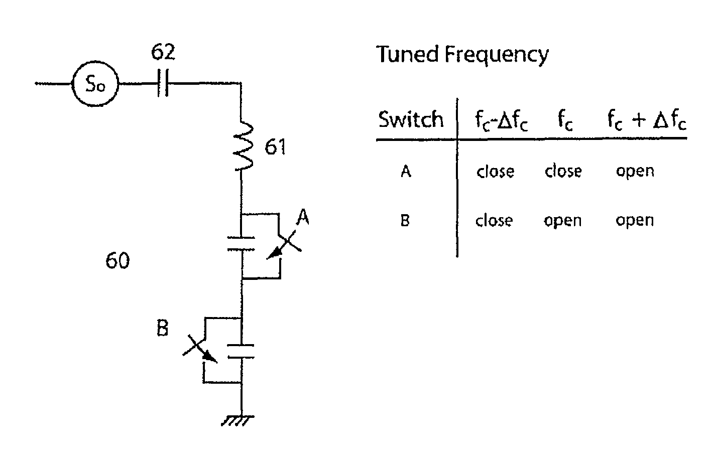
[0041]In essence, in the present invention, in order to pass phase modulated signals with relatively high data rates through relatively high Q narrow bandwidth circuits, the centre (resonant) frequency of the circuit is adjusted (shifted) to substantially match the instantaneous frequency of the phase modulated signal in other words, the tuning is ‘moved’ for relatively short periods of time during the modulated phase transitions. This has been found to result in the ability to get the relatively fast PJM phase transitions into the Interrogator's antenna for transmission to a transponder or other remote device.

Problems solved by technology

These circuits are often inherently narrow band and can not pass signals which are modulated at data rates greater than the circuit's bandwidth.

Method used


Image

  • Method and apparatus adapted to transmit data
  • Method and apparatus adapted to transmit data
  • Method and apparatus adapted to transmit data

Examples


Embodiment Construction

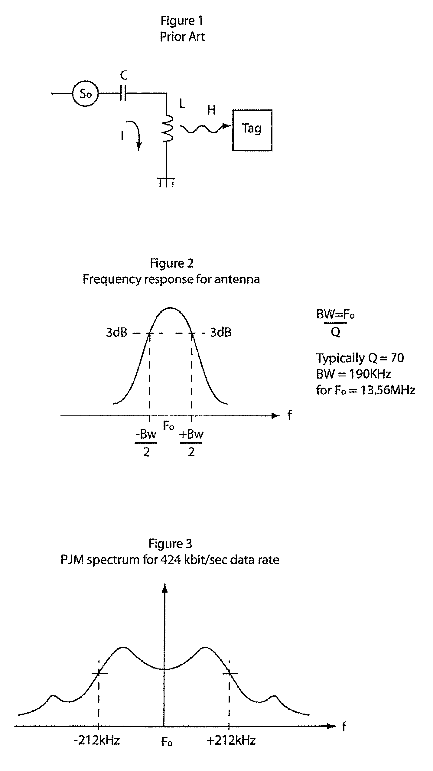
[0070]FIG. 1 illustrates schematically a circuit configuration associated with prior art excitation of tags. A signal source So provides a signal to a tuned coil (L,C) by virtue of current I, which in turn induces an excitation field H to be transmitted to a tag. The excitation field may include power and / or data.

[0071]FIG. 2 illustrates the bandwidth of the prior art circuit shown in FIG. 1 having a resonant frequency Fo, and a 3 dB bandwidth of BW (−BW / 2 to +BW / 2). In a typical application of the prior art technology, there is a bandwidth approximately 190 kHz (±80 kHz). This equates to an antenna having a Q factor of around 70, using the equation:

Q=Fo / Bandwidth  equation 1

[0072]In accordance with the present invention, it has been realised that when an antenna is used of powering a remote tag, an antenna having a relatively high Q factor, provides a relatively high efficiency. However, a relatively high Q factor in turn provides a relatively low bandwidth, as is illustrated in FI...


PUM


Abstract

The present invention relates to the field of data transmission. The invention has application to amplifiers, the transmission of data modulated signals, filters and / or matching circuits connected between an amplifier and a load, radio transmitters, the transmission of data modulated radio signals, filters and / or matching circuits used between a transmitter's power amplifier and an antenna and the field of Radio Frequency Identification (RFID), such as in the transmission of data between a tag and an interrogator. The present invention enables the transmission of phase modulated signals, by adjusting a device's tuning to substantially match the instantaneous frequency of the phase modulated signal.

Description

FIELD OF INVENTION[0001]The present invention relates to the field of data transmission.[0002]In one form, the invention relates to amplifiers and the transmission of data modulated signals.[0003]In another form, the invention relates to the filters and / or matching circuits connected between the amplifier and load and their ability to pass modulated signals.[0004]In another form, the invention relates to radio transmitters and the transmission of data modulated radio signals.[0005]In another form, the invention relates to the filters and / or matching circuits used between the transmitter's power amplifier and antenna and their ability to pass modulated signals[0006]In another form, the invention relates to the field of Radio Frequency Identification (RFID), and the transmission of data from a tag to an interrogator.[0007]In another form, the present invention is suitable for transmitting data via a single antenna.[0008]It will be convenient to hereinafter describe the invention in re...

Claims


Application Information

Patent Timeline
Patent Type & Authority Patents(United States)
IPC IPC(8): H04B1/04
CPCH03C3/06H03C3/12H04B5/0031H04B5/0037H04B5/0075H03H2210/012H03J2200/10
Inventor MURDOCH, GRAHAM ALEXANDER MUNRO
Owner SATO HLDG CORP
Learn More