Supercharge Your Innovation With Domain-Expert AI Agents!

System for calculating axial deformation of turbine rotor

a technology of axial deformation and turbine rotor, which is applied in the direction of mechanical roughness/irregularity measurement, electrical/magnetic diameter measurement, instruments, etc., can solve the problems of complicated calculation and enormous amount of calculation, and achieve accurate calculation

Active Publication Date: 2013-04-09
MITSUBISHI POWER LTD
View PDF12 Cites 0 Cited by
  • Summary
  • Abstract
  • Description
  • Claims
  • Application Information

AI Technical Summary

Benefits of technology

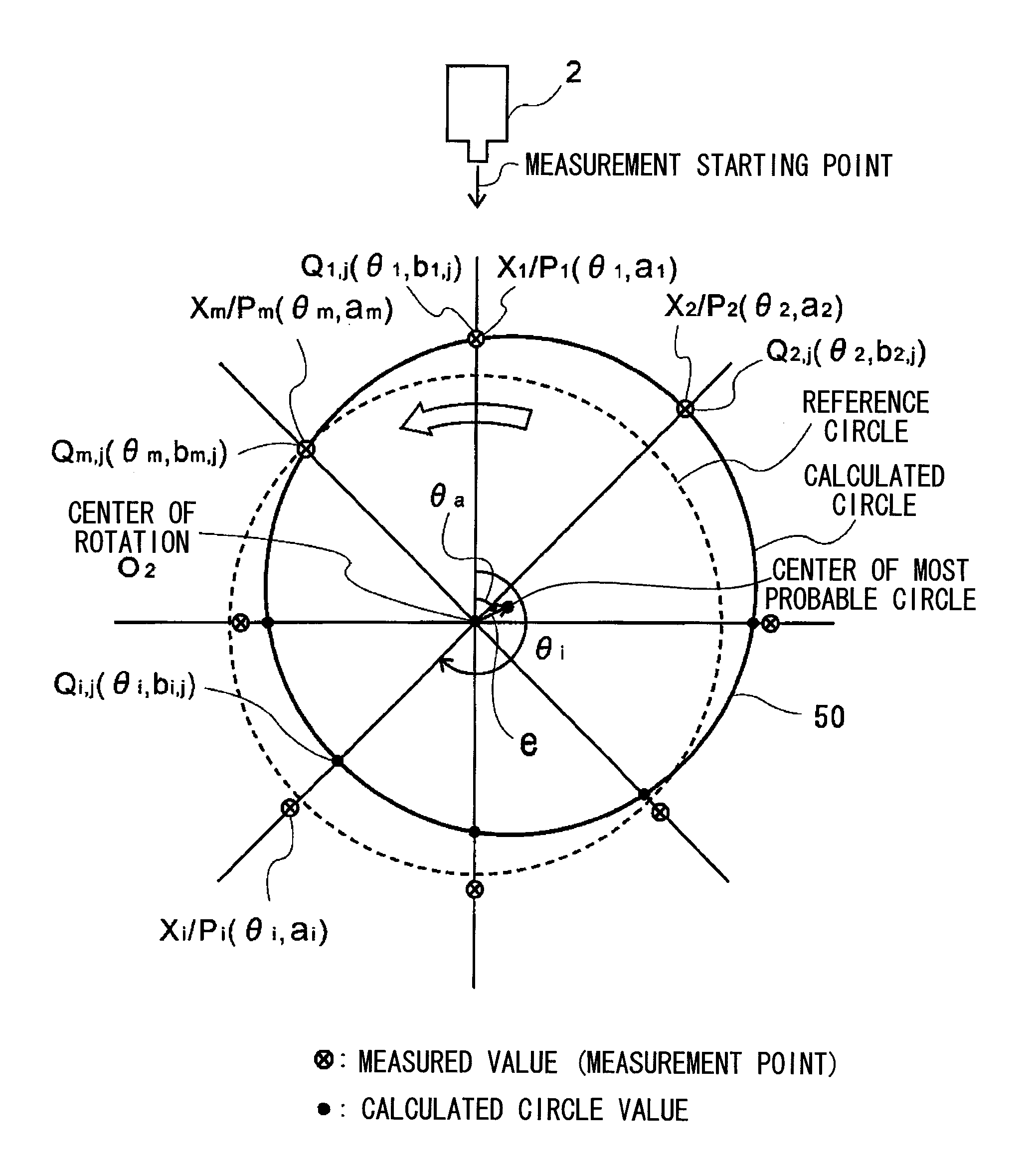
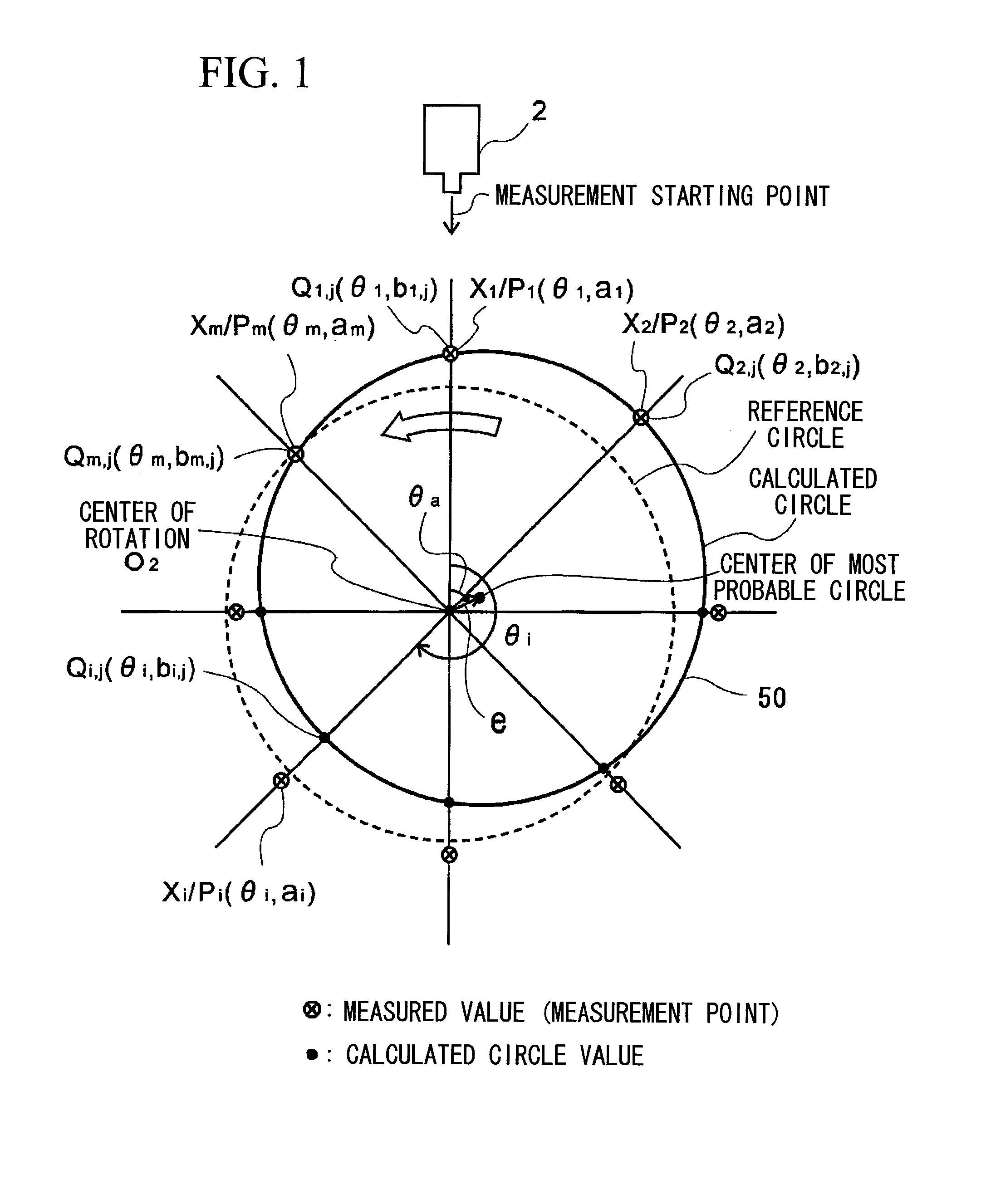
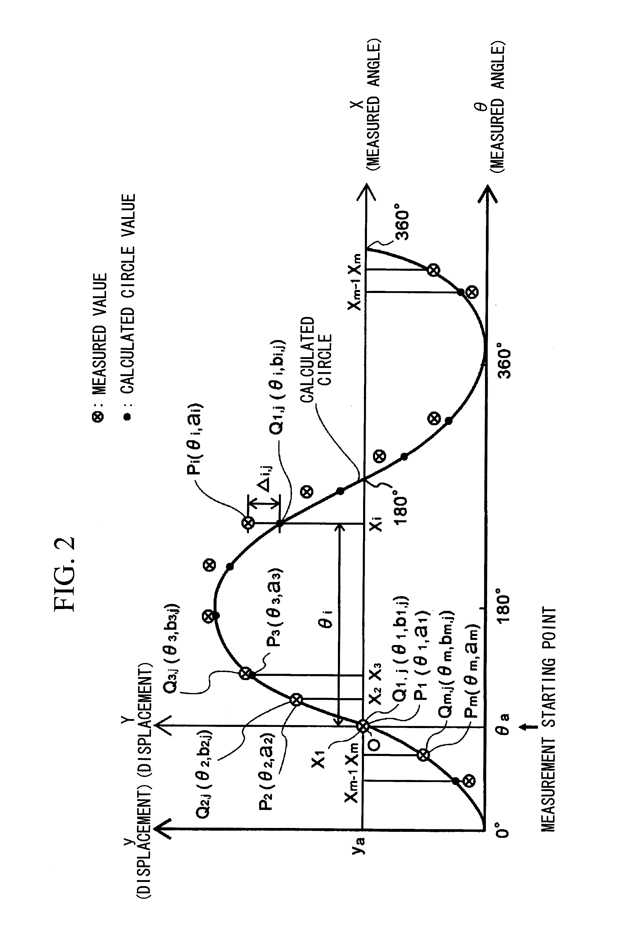
[0009]According to the present invention, at least four or more measurement points are set in the circumferential direction of the turbine rotor, the calculated circle is calculated from the displacement amount and the measured angle measured at each measurement point, the most probable circle is determined from the calculated circle, and the misalignment data of the most probable circle is calculated from the most probable circle, thereby allowing axial deformation to be calculated by a simpler method than conventional methods.
[0011]With this configuration, when the maximum misalignment amount exceeds the reference value, the corrected disk selection part selects the rotor disk to be corrected, and the correction amount determination part determines the correction amount of the rotor disk, thereby allowing the axial deformation of the turbine rotor to be easily corrected.
[0013]With this configuration, the rotor disk having the maximum misalignment amount is to be corrected, thereby minimizing the maximum misalignment amount after the correction of the rotor disk.
[0015]With this configuration, the disk correction amount is determined based on the maximum misalignment amount, thereby providing the simplest correction method and minimizing the axial deformation of the turbine rotor after the correction of the rotor disk.
[0016]According to the present invention, the most probable circle can be easily selected, and thus axial deformation of the rotor can be calculated accurately by a simple method without an enormous amount of calculation as disclosed in JP '244.

Problems solved by technology

However, the conventional method disclosed in JP '244 is a calculation method with high accuracy, but has a problem that calculation is complicated and an enormous amount of calculation is required.

Method used


Image

  • System for calculating axial deformation of turbine rotor
  • System for calculating axial deformation of turbine rotor
  • System for calculating axial deformation of turbine rotor

Examples


Embodiment Construction

[0059]An embodiment of the present invention will be described with reference to the drawings, which merely show the embodiment by way of example, and the present invention is not limited to the embodiment. Components in the embodiment include components easily replaceable by those skilled in the art, or substantial equivalents. A gas turbine rotor will be described below by way of example.

[0060]FIG. 8 shows a general structure of a gas turbine rotor. The gas turbine rotor 1 includes a compressor rotor part 10, a turbine rotor part 20, and an intermediate shaft 25 connecting the rotor parts, and the compressor rotor part 10 and the turbine rotor part 20 are each constituted by disk-shaped rotor disks 50 including blades 11 radially implanted in an outer periphery. The gas turbine rotor 1 is an assembly having an integral structure in which the rotor disks 50 are placed one next to another in a rotor axis direction and fastened by spindle bolts 30, and opposite ends thereof are suppo...


PUM


Abstract

A system calculates axial deformation of a turbine rotor. The system includes an input part that sets measurement points of rotor disks that constitute the turbine rotor; a deflection amount detection part that derives radial displacement amounts of the turbine rotor for at least four or more measurement points along an outer surface in a circumferential direction of the turbine rotor based on measured values measured by a displacement gage; a storage part that stores the radial displacement amounts and measured angles at the measurement points; and a calculation part that calculates misalignment data of a most probable circle of the turbine rotor based on data stored. The calculated circle is calculated from the displacement amount and the measured angles. The most probable circle is determined from the calculated circle, and the misalignment data of the most probable circle is calculated from the most probable circle.

Description

RELATED APPLICATIONS[0001]The present application is a National Phase of International Application Number PCT / JP2008 / 061865, filed Jun. 30, 2008, the disclosure of which is hereby incorporated by reference herein in its entirety.TECHNICAL FIELD[0002]The present invention relates to a system for calculating axial deformation of a turbine rotor.BACKGROUND ART[0003]Generally, axial deformation or misalignment that occurs in a turbine rotor causes imbalance of the turbine rotor, which may cause shaft vibration during operation. Excessive shaft vibration causes an abnormality in a bearing part and prevents normal operation. A further progress of the excessive vibration may lead to a break of the shaft. Thus, to prevent such a break, it is important to keep axial deformation or alignment of the turbine rotor within an acceptable value.[0004]Turbine rotors covered by the present invention include a gas turbine rotor and also a steam turbine rotor.DISCLOSURE OF INVENTION[0005]Generally, for...

Claims


Application Information

Patent Timeline
Patent Type & Authority Patents(United States)
IPC IPC(8): G01C9/00G01B3/00G01B5/00
CPCG01B5/252G01B21/24
Inventor IHARA, KEISUKESAKAE, TOSHIYUKI
Owner MITSUBISHI POWER LTD
Features
  • R&D
  • Intellectual Property
  • Life Sciences
  • Materials
  • Tech Scout
  • Unparalleled Data Quality
  • Higher Quality Content
  • 60% Fewer Hallucinations
Learn More