Spoiler deployment mechanism

a technology of a deployment mechanism and a wing, which is applied in the direction of wing adjustment, air braking surface, wings, etc., can solve the problems of unsuitability of conventional mechanisms, and achieve the effect of less spa

Inactive Publication Date: 2013-04-16
AIRBUS OPERATIONS LTD
View PDF41 Cites 9 Cited by
  • Summary
  • Abstract
  • Description
  • Claims
  • Application Information

AI Technical Summary

Benefits of technology

[0010]The use of a linkage mechanism in combination with a pivoting actuator enables the deployment mechanism to take up less space in a girth-wise direction since the stroke of the actuator can act in a predominantly span-wise direction. It also enables a larger and more powerful actuator to be used if necessary.
[0011]The actuator may be attached to the upper link or the lower link at a distal pivot which is spaced apart from the central pivot. This can provide an element of mechanical advantage. For instance the distal pivot may attach the actuator to the upper link, and the central pivot is located between the distal pivot and the upper pivot. Alternatively the distal pivot which attaches the actuator to the linkage mechanism may be co-axial with the central pivot which attaches the lower link of the linkage mechanism to the upper link of the linkage mechanism. This makes for a more compact arrangement.

Problems solved by technology

In future aircraft, the girth-wise space available behind the rear spar is becoming increasingly small, making such conventional mechanisms unsuitable.

Method used


Image

  • Spoiler deployment mechanism
  • Spoiler deployment mechanism
  • Spoiler deployment mechanism

Examples


Embodiment Construction

)

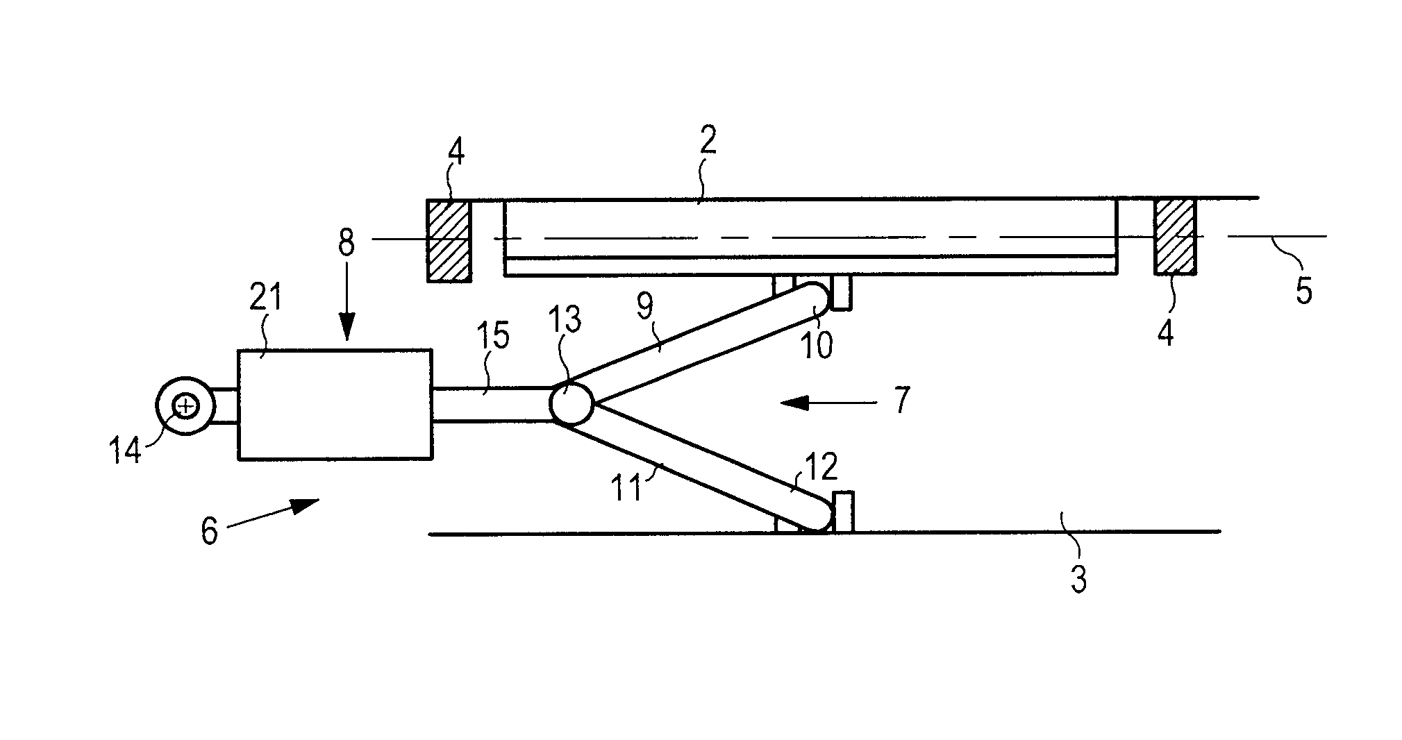
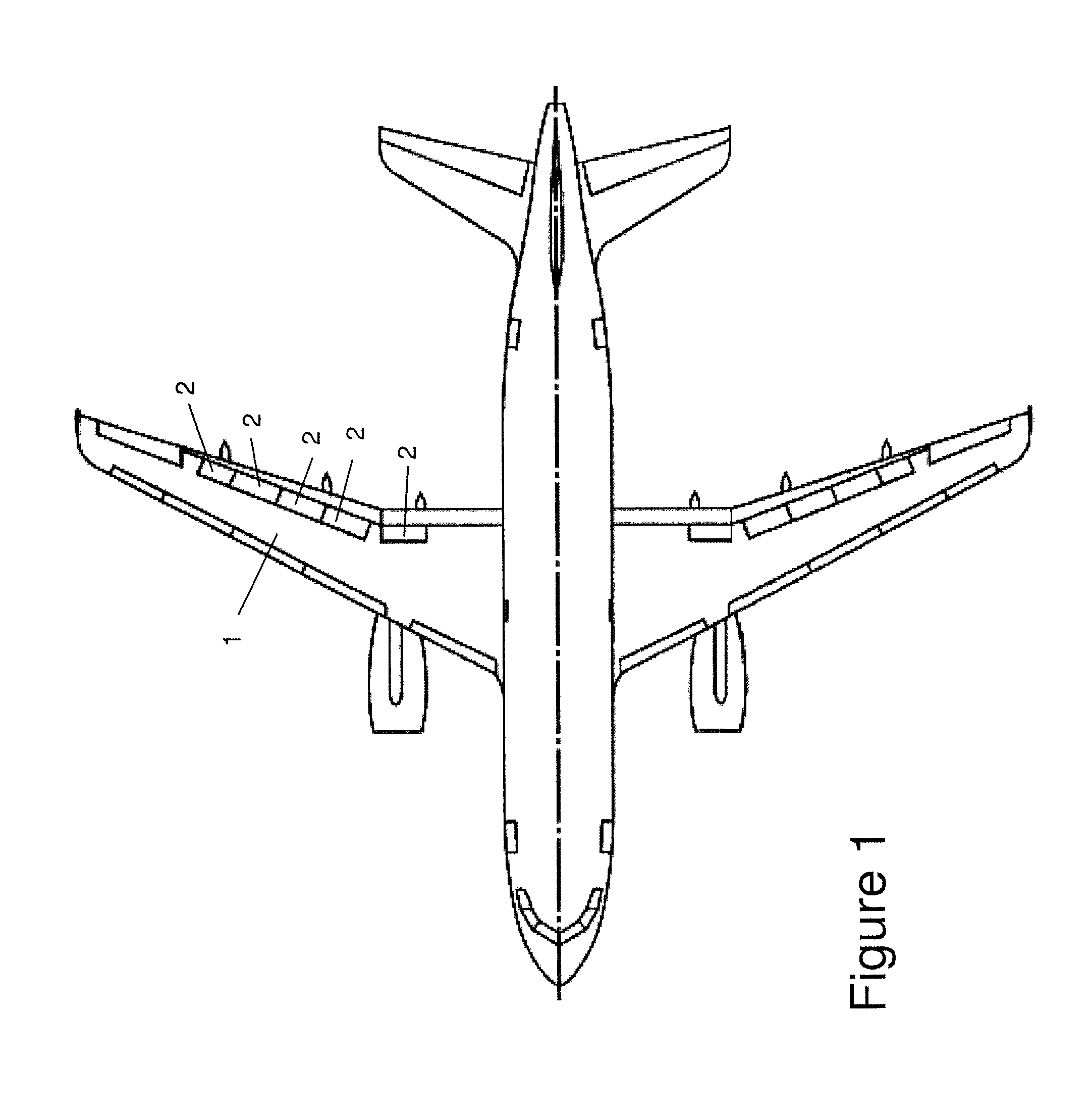
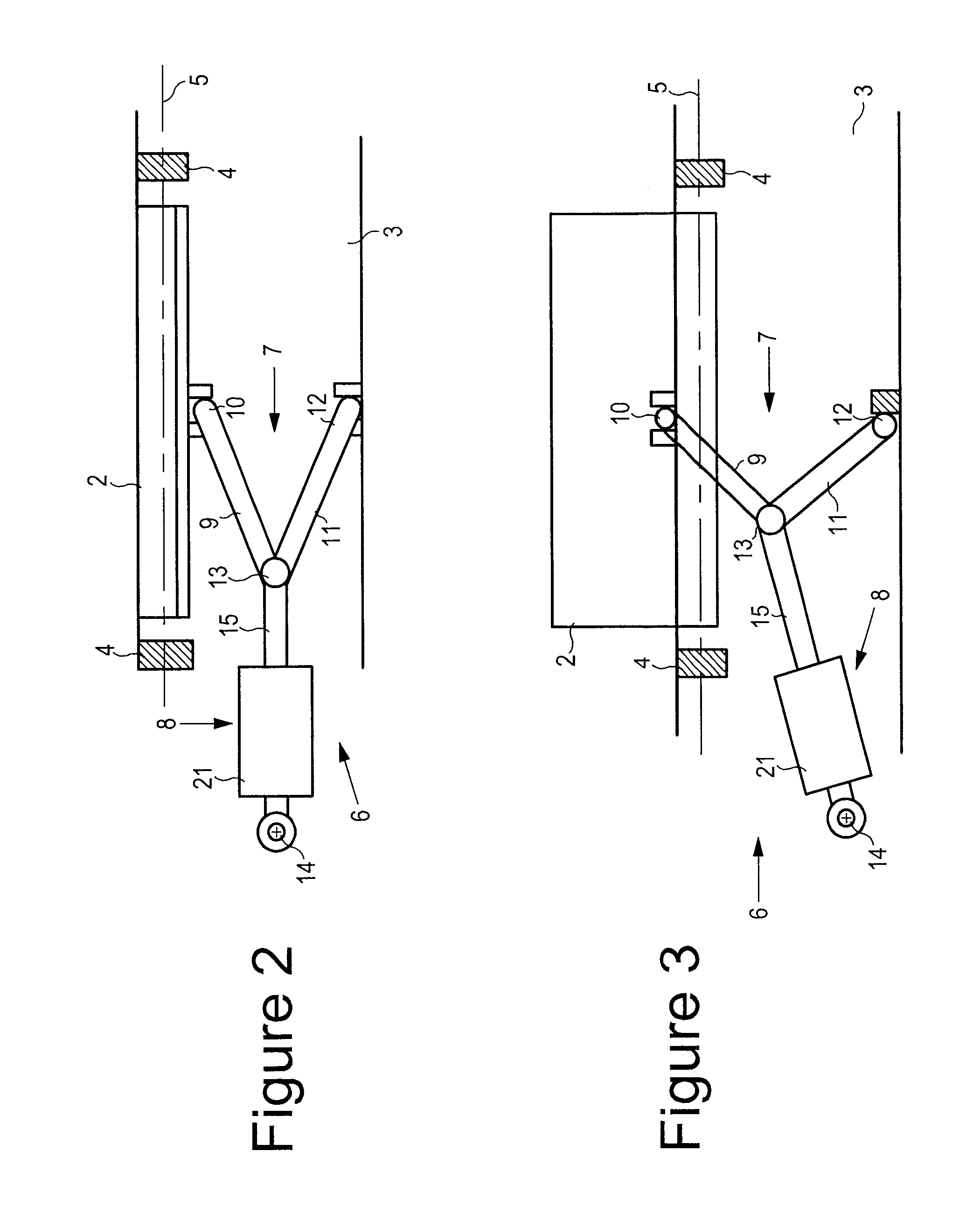
[0025]An aircraft shown in FIG. 1 comprises a wing 1 with a series of spoilers 2 (otherwise known as air brakes or lift dumpers) on its upper surface. One of these spoilers 2 is shown in FIGS. 2-5. The wing comprises a rear spar 3 to which the spoiler 2 is pivotally attached by a pair of hinges 4. The spoiler pivot line 5 provided by these hinges 4 remains fixed as the spoiler is deployed.

[0026]The spoiler 2 is rotated about the pivot line 5 by a spoiler deployment mechanism 6 comprising a scissor linkage mechanism 7 and a linear actuator 8. The scissor linkage mechanism 7 comprises an upper link 9 pivotally attached to the spoiler at an upper pivot 10, and a lower link 11 pivotally attached to the spar 3 at a lower pivot 12 and to the upper link 9 at a central pivot 13.

[0027]The lower hinge mechanism at the lower pivot 12 is shown in detail in FIGS. 6 and 7. The lower link 11 is pivotally attached to a hinge member 17 via a clevis joint which permits the link to pivot about an axi...


PUM


Abstract

An aircraft wing assembly comprising: a wing; a spoiler pivotally attached to the wing; and a spoiler deployment mechanism. The deployment mechanism comprises a scissor linkage mechanism comprising an upper link pivotally attached to the spoiler at an upper pivot, and a lower link pivotally attached to the wing at a lower pivot and to the upper link at a central pivot. An actuator is pivotally attached to the wing at a proximal pivot and to the scissor linkage mechanism at a distal pivot. The actuator is adjustable between expanded and contracted configurations so as to vary the distance between the proximal and distal pivots. This opens up the angle between the upper and lower links of the scissor linkage mechanism and pushes the spoiler up into the air-stream above the wing.

Description

RELATED APPLICATIONS[0001]The present application is a national phase of PCT / GB2009 / 050432, filed Apr. 28, 2009, and claims priority from, Great Britain Application Number 0808349.5, filed May 9, 2008.FIELD OF THE INVENTION[0002]The present invention relates to an aircraft wing assembly comprising: a wing; a spoiler pivotally attached to the wing; and a spoiler deployment mechanism.BACKGROUND OF THE INVENTION[0003]Conventional spoiler deployment mechanisms comprise a linear actuator pivotally attached to the wing at a proximal pivot and to the spoiler at a distal pivot. The actuator is oriented in a girth-wise (wing depth) direction. In future aircraft, the girth-wise space available behind the rear spar is becoming increasingly small, making such conventional mechanisms unsuitable.[0004]DE737445 describes an aircraft wing with a number of air brakes which extend partially along the span of the wing. A linkage mechanism can be operated to move the air brakes vertically between retra...

Claims


Application Information

Patent Timeline
Patent Type & Authority Patents(United States)
IPC IPC(8): B64C25/50
CPCB64C3/58B64C9/323B64C9/32Y10T74/18944
Inventor ALLEN, DAMIAN
Owner AIRBUS OPERATIONS LTD
Why Eureka
Try Eureka