Ophthalmic examination system interface device

a technology of interface device and ophthalmology, which is applied in the field of ophthalmological examination systems, can solve problems such as compatibility problems, and achieve the effect of facilitating communication

Active Publication Date: 2013-04-16
THE HILSINGER
View PDF15 Cites 9 Cited by
  • Summary
  • Abstract
  • Description
  • Claims
  • Application Information

AI Technical Summary

Benefits of technology

[0009]In yet another aspect, an interface device is utilized to communicate data between a refraction system and a display within an automated ophthalmic system. A first data port receives a voltage signal from the refraction system. A second data port facilitates communication between the display and the interface device. A voltage detector detects a predefined voltage change from the voltage signal received by the first data port. An ASCII converter associates one or more ASCII characters with the voltage change detected by the voltage detector. An I / O controller communicates the one or more ASCII characters from the interface device to the display via the second data port.

Problems solved by technology

Compatibility issues can arise, however, when communication is attempted between a refraction system and a computer-based eye chart produced by disparate manufacturers.

Method used


Image

  • Ophthalmic examination system interface device
  • Ophthalmic examination system interface device
  • Ophthalmic examination system interface device

Examples


Embodiment Construction

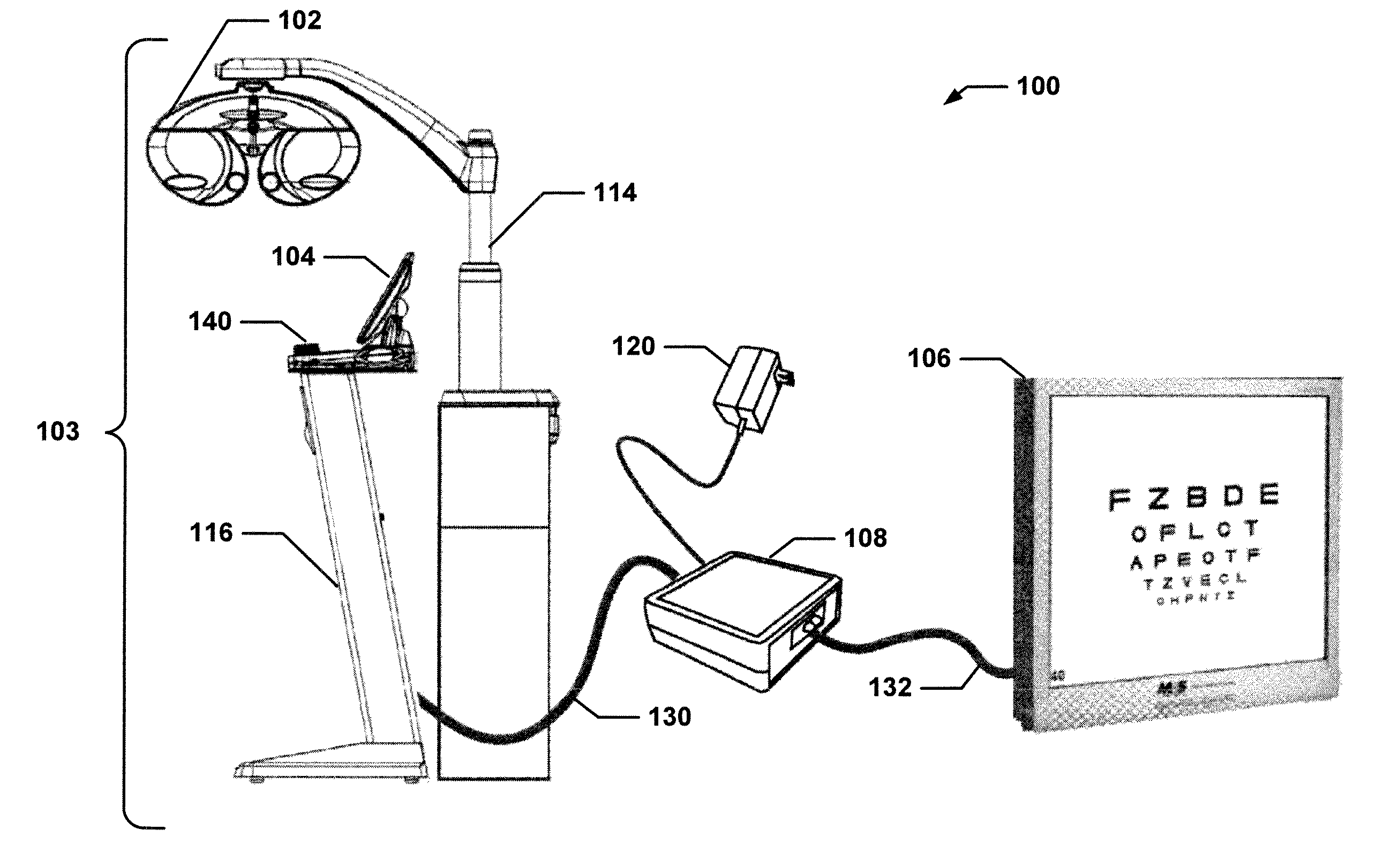
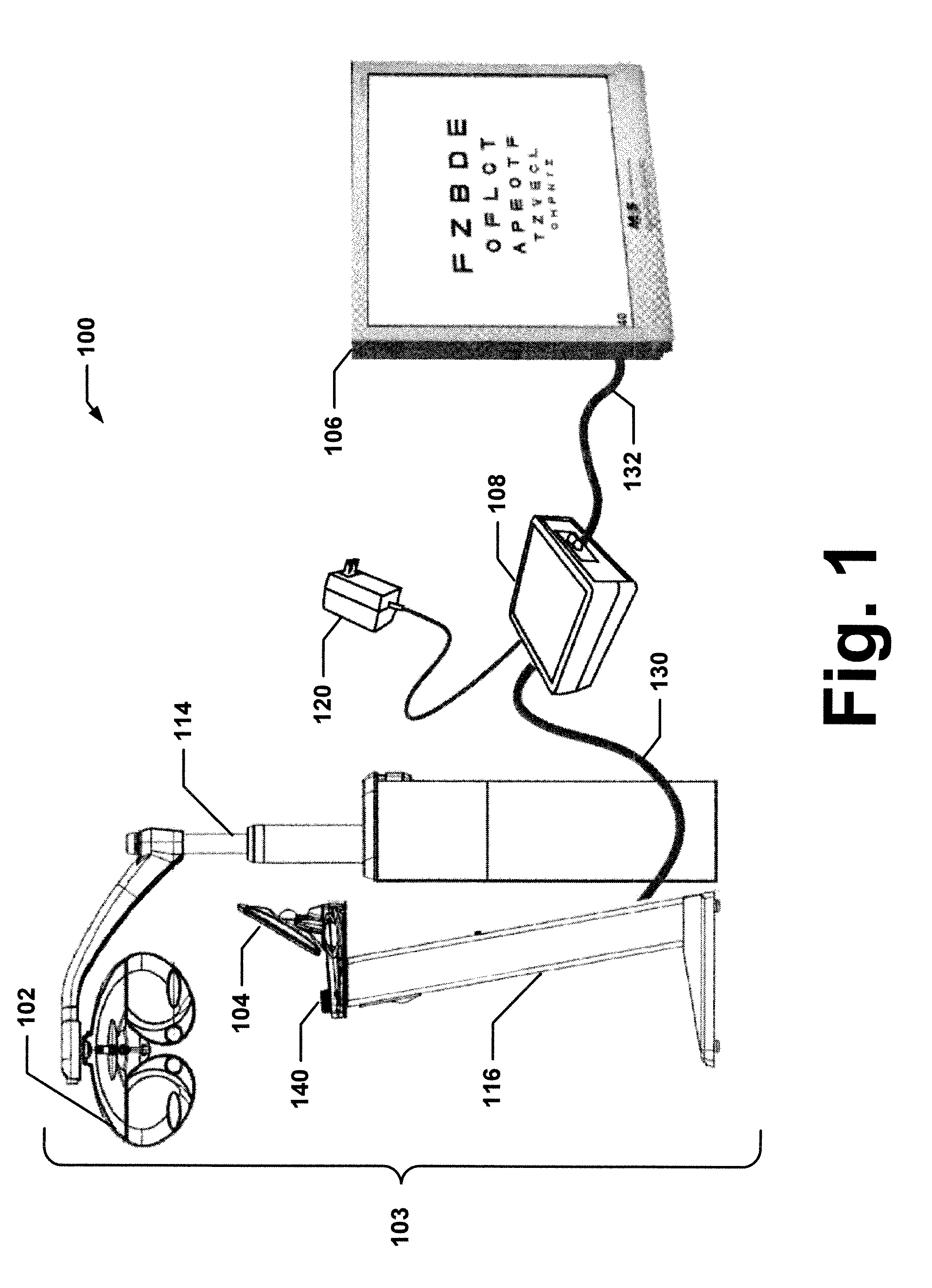
[0015]FIG. 1 illustrates an automated ophthalmic examination system 100 that is utilized to perform eye examinations on subjects. A phoroptor 102 is operated via a user interface 104 to measure a subject's refractive error and to determine an appropriate corrective lens for compensation thereof. The phoroptor 102 and the user interface 104 comprise a refraction system 103 that evaluates vision by presentation of images, such as via a display 106, as viewed by the subject through a plurality of disparate lenses. The user interface 104 is coupled to the display component 106 via an interface device 108. The refraction system 103 can connect to the interface device 108 via a cable 130. The interface device 108 can connect to the display 106 via a cable 132.

[0016]Substantially any design, such as coaxial, twisted pair, etc., is contemplated for the cables 130 and 132. Further, substantially any pin configuration and / or connector such as an RJ45 connector, a 7-pin DIN connector, a USB co...


PUM


Abstract

An automated ophthalmic system is disclosed that is utilized to examine the eyes of a subject. A refraction system measures a refractive error of each eye and identifies a lens to correct the refractive error detected. A display presents one or more of an optotype, a chart, a test and a function to the subject to ascertain the refractive error. An interface device receives a voltage signal from the refraction system, converts the voltage signal into one or more ASCII characters, and communicates the one or more ASCII characters to the display to present the one or more of an optotype, a chart, a test and a function.

Description

[0001]This application claims the benefit of U.S. application Ser. No. 61 / 060,241, filed Jun. 10, 2008, the disclosure of which is incorporated herein by reference.BACKGROUND[0002]The present exemplary embodiments relate generally to ophthalmic examination systems. In one particular application, an interface device is utilized to facilitate communication between a refraction system and a display within the ophthalmic examination system. However, it is to be appreciated that the present exemplary embodiment is also amenable to other like applications.[0003]An eye examination is a battery of tests performed by an optometrist or ophthalmologist to assess a subject's vision and ability to focus on and discern objects. An automated ophthalmic exam system can be employed to aid in the determination of a subject's refractive error and to identify an appropriate lens prescription to correct such error. In one example, an automated ophthalmic system includes a phoroptor and an eye chart. The...

Claims


Application Information

Patent Timeline
Patent Type & Authority Patents(United States)
IPC IPC(8): A61B3/10A61B3/00
CPCA61B3/0285A61B3/032A61B3/103
Inventor BUTLER, KEVIN A.WHITTENBURG, MICHAEL C.
Owner THE HILSINGER
Why Eureka
Try Eureka