Linear vacuum robot with Z motion and articulated arm

a vacuum robot and linear motion technology, applied in mechanical equipment, transportation and packaging, coatings, etc., can solve the problems of increasing costs, increasing risks in undertaking investments, and extremely high costs of manufacturing semiconductors, so as to reduce the risk of undertaking investments, reduce the cost of manufacturing semiconductors, and increase the effect of cos

Active Publication Date: 2013-04-16
BOOKS AUTOMATION US LLC
View PDF39 Cites 97 Cited by
  • Summary
  • Abstract
  • Description
  • Claims
  • Application Information

AI Technical Summary

Benefits of technology

This invention is a new kind of semiconductor processing unit that allows for separate control of processing times at different stations while keeping the footprint small. It also enables continued operation even if one or more stations fails. The goal is to lower costs and improve efficiency in manufacturing semiconductors. The system has a small footprint and maximizes processing chambers and station utilization. It also offers redundancy in case of failure and allows for adding more functional stations without needing to increase the size or create new total systems. The invention also includes a method for transferring wafers from a loadlock to a processing chamber using a robot arm in an evacuated transfer chamber. The method includes magnetically coupling linear and rotational motion to the robot arm for linear and elevated transport of the wafer in the evacuated transfer chamber.

Problems solved by technology

In part this is in recognition that the cost of manufacturing semiconductors is extremely high and costs are increasing.
The higher the costs, the greater the risks in undertaking investments in this field.
The system will also offer considerable redundancy, including up to 100% availability of the system for processing even during mainframe servicing.

Method used


Image

  • Linear vacuum robot with Z motion and articulated arm
  • Linear vacuum robot with Z motion and articulated arm
  • Linear vacuum robot with Z motion and articulated arm

Examples


Embodiment Construction

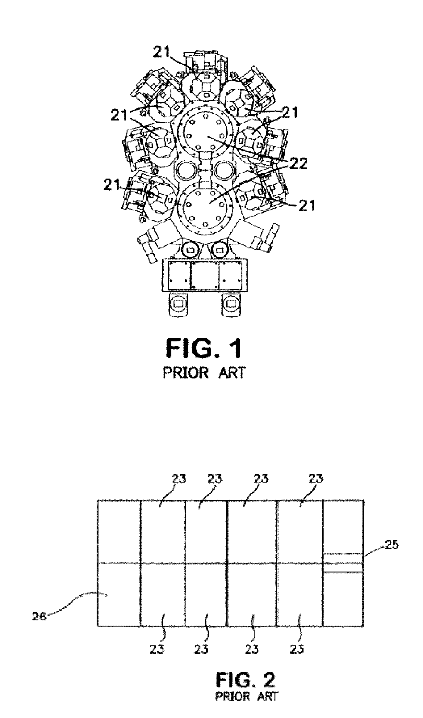
[0039]Referring now to FIG. 1, there is illustrated a cluster tool of the type commonly in use today. In general this comprises processing chambers 21 radially disposed around and attached to central chambers 22. In this system, there are two central chambers. Other systems may have only a single central chamber. A system with more than two can exist except that it is cumbersome and instead users will generally acquire another system. In operation, a robot is typically located within each central chamber 22. The robot receives wafers into the system and carries wafers from the central chamber to processing chambers and after processing back to the central chamber. In some prior art systems, a central robot can access only a single wafer and single chamber at one time. Thus the robot can become engaged or busy during processing in connection while a wafer is in a single chamber. This combination of a single robot tied to a processing station during processing is a limitation on the t...


PUM

PropertyMeasurementUnit
diameteraaaaaaaaaa
diameteraaaaaaaaaa
diameteraaaaaaaaaa

Abstract

There is described apparatus and methods for transporting and processing substrates including wafers as to efficiently produce at reasonable costs improved throughput as compared to systems in use today. A linear transport chamber includes linear tracks and robot arms riding on the linear tracks to linearly transfer substrates along the sides of processing chambers for feeding substrates into a controlled atmosphere through a load lock and then along a transport chamber as a way of reaching processing chambers. A four-axis robot arm is disclosed, capable of linear translation, rotation and articulation, and z-motion.

Description

RELATED APPLICATIONS[0001]This application is a Continuation-in-Part of U.S. application Ser. No. 11 / 523,101, filed Sep. 19, 2006 now U.S. Pat. No. 7,901,539, of U.S. application Ser. No. 12 / 325,993, filed Dec. 1, 2008, and of U.S. patent application Ser. No. 12 / 368,241, filed Feb. 9, 2009. This application also claims priority benefit from U.S. Provisional Application Ser. No. 61 / 259,928, filed Nov. 10, 2009. The disclosures of all which applications are incorporated herein by reference in their entirety.FIELD OF THE INVENTION[0002]This invention has to do with novel apparatus and methods for transporting and processing substrates in general and wafers in particular. More specifically, the invention relates to linear motion vacuum robots having z-motion and articulated arm.BACKGROUND[0003]In the manufacture of semiconductors, a common tool, referred to as a cluster tool, is one of the key units used in the manufacture of wafers. A typical commercial device has a generally polygonal...

Claims


Application Information

Patent Timeline
Patent Type & Authority Patents(United States)
IPC IPC(8): B65G1/133C23C16/00C23F1/00H01L21/306
CPCH01L21/67173H01L21/67184H01L21/67201H01L21/677H01L21/67745Y10T74/20323Y10T74/20317H01L21/67742H01L21/67196
Inventor HOEY, GEE SUNBLUCK, TERRYVU, HOANG HUYRYU, JIMIN
Owner BOOKS AUTOMATION US LLC
Why Eureka
Try Eureka