
Apparatus and method for controllable downhole production of ionizing radiation without the use of radioactive chemical isotopes

a technology of ionizing radiation and apparatus, which is applied in the direction of instruments, x-ray tubes, x-ray tube details, etc., can solve the problems of difficult balance between economy and safety, inability to use non-radioactive systems capable of producing photon energy, and high infrastructure costs, so as to reduce the risk of sparking and good insulation properties

Active Publication Date: 2013-07-09
VISURAY TECH
View PDF11 Cites 34 Cited by
  • Summary
  • Abstract
  • Description
  • Claims
  • Application Information

AI Technical Summary

Benefits of technology

The patent text discusses the trade-off between safety and economy when using isotopes for oil and gas well monitoring. The longer the monitoring takes, the higher the costs associated with the infrastructure and the risk of losing production. To address this problem, the patent proposes to use sulphur hexafluoride as an electrically insulating substance to reduce the time required for the monitoring.

Problems solved by technology

With the prior art it has not been possible to use non-radioactive systems capable of producing the photon energies required in order to replace the emitted energy of conventional radioactive isotopes used in logging operations in boreholes and the like, that is to say an apparatus which has X-ray / gamma radiation greater than 200 keV and is arranged in a housing with a diameter of less than 4″ (101 mm).
This leads to a difficult balance between economy and safety; the longer a logging operation takes, the higher the costs associated with the infrastructure (such as drilling-rig time) and / or loss of production; and the shorter the logging operation time is, the greater risk attaches to the isotope used, and the more extensive safety precautions must be taken when handling the isotope.

Method used


Image

  • Apparatus and method for controllable downhole production of ionizing radiation without the use of radioactive chemical isotopes
  • Apparatus and method for controllable downhole production of ionizing radiation without the use of radioactive chemical isotopes
  • Apparatus and method for controllable downhole production of ionizing radiation without the use of radioactive chemical isotopes

Examples


Embodiment Construction

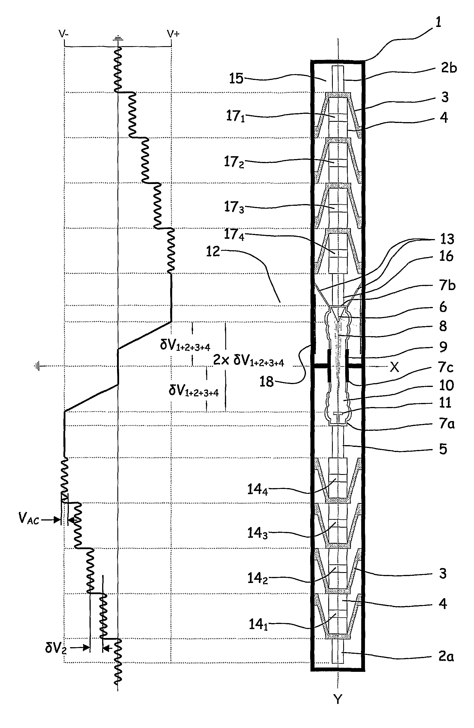
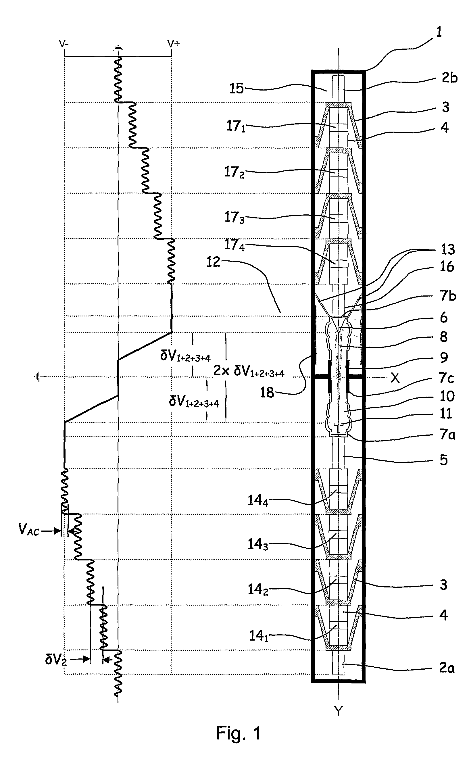
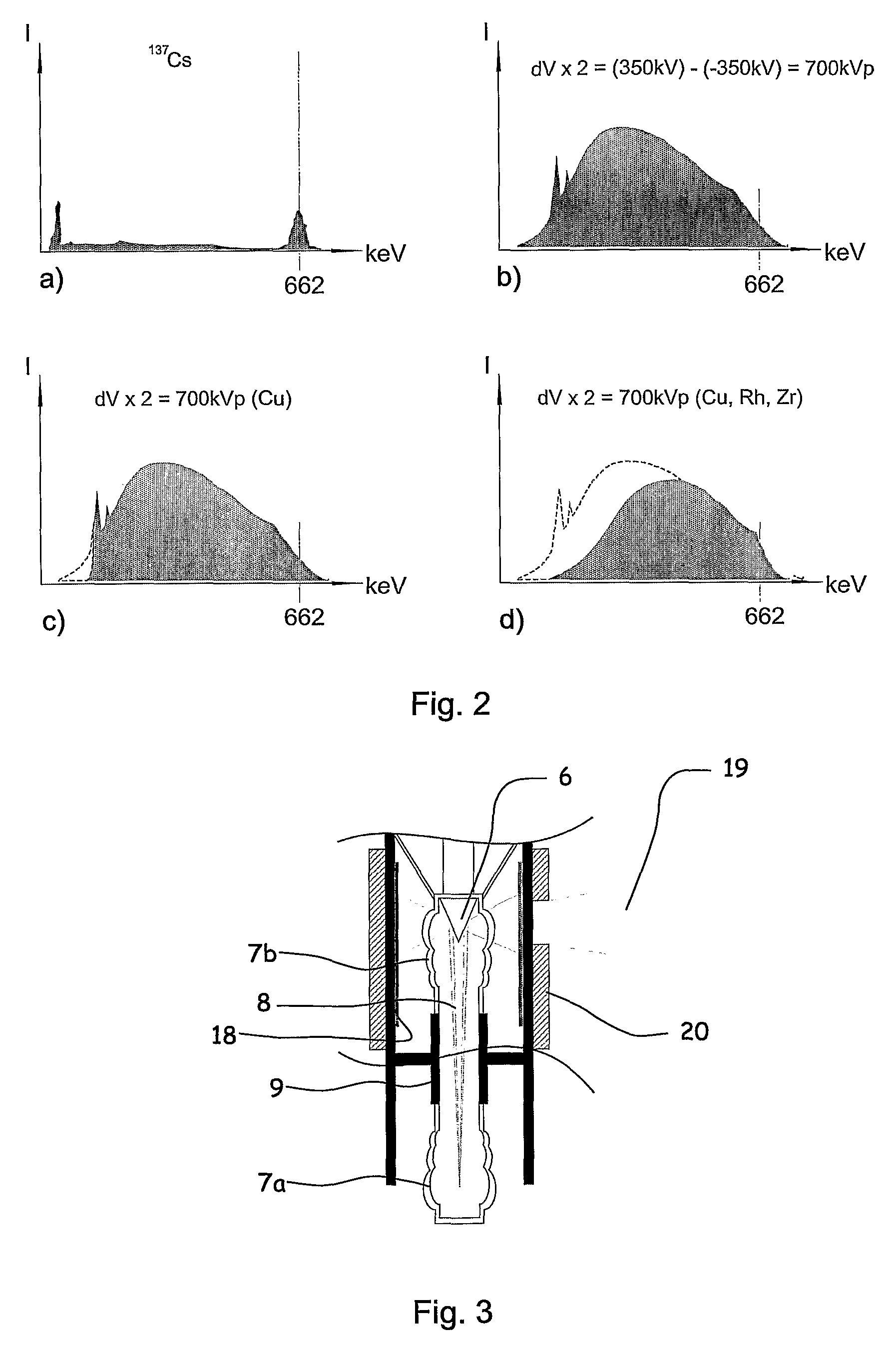
[0046]In the figures, the reference numeral 1 indicates a fluids tight, cylindrical housing with an outer diameter which does not exceed 4″ (101 mm). The housing 1 is rotationally symmetrical around a longitudinal axis and is arranged to be electrically grounded. The housing 1 is preferably arranged to be pressurized with an electrically insulating substance 15 in gaseous form, sulphur hexafluoride in one embodiment. A thermionic emitter 6, and a lepton target, are arranged in a cylindrical vacuum container 9 which is provided by two electrically insulating caps 7a, 7b forming closed end portions of a tube 7c which is electrically connected to the enveloping housing 1, said container 9 thereby forming an electrically grounded support structure as well as an electrical-field-focussing tube.

[0047]In the preferred embodiment no detector system is included in the apparatus for the purpose of assisting in the data acquisition during the logging operation, but if desired, shielded photon ...


PUM


Abstract

Apparatus for the controllable downhole production of ionizing radiation (12), the apparatus including at least a thermionic emitter (11) which is arranged in a first end portion (7a) of an electrically insulated vacuum container (9), and a lepton target (6) which is arranged in a second end portion (7b) of the electrically insulated vacuum container (9); the thermionic emitter (11) being connected to a series of serially connected negative electrical-potential-increasing elements (141, 142, 143, 144), each of said electrical-potential-increasing elements (141, 142, 143, 144) being arranged to increase an applied direct-current potential (δV0, δV1, δV1+2, . . . , δV1+2+3) by transforming an applied, driving voltage (VAC), and to transmit the increased, negative direct-current potential (δV1, δV1+2, . . . , δV1+2+3+4) and also the driving voltage (VAC) to the next unit in the series of serially connected elements (141, 142, 143, 144,5), and the ionizing radiation (12) exceeding 200 keV with a predominant portion of the spectral distribution within the Compton range.

Description

CROSS REFERENCE TO RELATED APPLICATIONS[0001]The present application is a 35 U.S.C. §371 National Phase conversion of PCT / NO2010 / 000372, filed Oct. 20, 2010, which claims benefit of Norwegian Application No. 20093204, filed Oct. 23, 2009, the disclosure of which is incorporated herein by reference. The PCT International Application was published in the English language.SUMMARY OF THE INVENTION[0002]An apparatus for the controllable, downhole production of ionizing radiation is described, more particularly characterized by the apparatus including at least a thermionic emitter which is arranged in a first end portion of an electrically insulated vacuum container, and a lepton target which is arranged in a second end portion of the electrically insulated vacuum container; the thermionic emitter being connected to a series of serially connected negative electrical-potential-increasing elements, each of said electrical-potential-increasing elements being arranged to increase an applied d...

Claims


Application Information

Patent Timeline
Patent Type & Authority Patents(United States)
IPC IPC(8): G01V5/00
CPCH01J35/32H01J35/02H05G1/12H01J35/116
Inventor TEAGUE, PHIL
Owner VISURAY TECH
Learn More