Cooling arrangement for a supercharged internal combustion engine

a technology of internal combustion engine and cooling arrangement, which is applied in the direction of machines/engines, mechanical equipment, non-fuel substance addition to fuel, etc., can solve the problems of ice formation in the radiator, water condensed in the radiator may freeze to ice, and the risk of ice formation is greater

Inactive Publication Date: 2011-02-24
SCANIA CV AB
View PDF22 Cites 29 Cited by
  • Summary
  • Abstract
  • Description
  • Claims
  • Application Information

AI Technical Summary

Benefits of technology

The object of the present invention is to provide an arrangement whereby a gaseous medium which contains water vapour can be subjected to very good cooling in a radiator while at the same time the risk of the radiator being obstructed is substantially eliminated.
This object is achieved with the arrangement of the kind mentioned in the introduction which is characterised by the features indicated in the characterising part of claim 1. For it to be possible for the gaseous medium to be effectively cooled, it needs to be cooled by a coolant which is at a low temperature. However, if the coolant in the second cooling system is colder than 0° C., there is obvious risk that the water which has condensed in the radiator may freeze to ice. The lower the temperature of the coolant in the second cooling system, the greater this risk. The arrangement therefore comprises also a first cooling system with a warmer coolant than the coolant in the second cooling system. The first cooling system is with advantage the cooling system which cools the combustion engine, in which the coolant may be at a temperature of the order of 80-85° C. According to the invention, a connecting line with a first valve means is used to make it possible to supply warm coolant from the first cooling system to the second cooling system. During normal operation of the combustion engine, the first valve means is placed in a first position whereby coolant from the first system is prevented from being led to the second cooling system. When the first valve means is placed in a second position, warm coolant from the first cooling system is allowed to be led to the second cooling system, in which the coolant is led in a direction such that it passes through said radiator. Such a supply of warmer coolant to the radiator in the second cooling system is favourable in situations where ice formation might occur in the radiator. If ice has formed within the radiator, the warm coolant from the first cooling system will melt the ice quickly and effectively. When the ice has melted, the first valve means is placed back in its first position. With such an arrangement, the gaseous medium can provide very good cooling in the radiator while at the same time any ice formation in the radiator can be eliminated simply and effectively.
According to a preferred embodiment of the invention, the arrangement comprises a second connecting line which connects the first cooling system to the second cooling system, and a second valve means which can be placed in a first position whereby it prevents coolant from the second cooling system from being led to the first cooling system via said second connecting line, and a second position whereby it allows the coolant which has passed through the radiator to be led back to the first cooling system via said second connecting line. Such a second connecting line makes it possible for the coolant to be led back to the first cooling system as soon as it has passed the portion of the second cooling system which comprises the radiator. With advantage, the flow of the cold coolant in the second system is halted in situations where warm coolant is supplied to the second cooling system. To this end, the control unit may halt the operation of a pump or the like which is adapted to circulating the existing coolant in the second cooling system.
According to a preferred embodiment of the invention, the arrangement comprises a control unit adapted to controlling the respective valve means and at least one sensor adapted to detecting a parameter which indicates whether the gaseous medium is cooled to such an extent that there is ice formation or risk of ice formation in the radiator, the control unit being adapted to receiving information from said sensor and to deciding whether there is ice formation or risk of ice formation in the radiator and, if so, to placing the first valve means and the second valve means in the second position. Such a control unit makes it possible for the valve means to be placed automatically in their second position as soon as ice formation occurs or is suspected of occurring in the radiator. The control unit may be a computer unit with software suitable for this purpose. Said sensor may be a temperature sensor which detects the temperature of the coolant in the second cooling system. If the temperature of the coolant is definitely below 0° C. when it is led into the radiator, there is obvious risk that ice formation may occur in the radiator. The arrangement may alternatively comprise temperature sensors or pressure sensors adapted to detecting a parameter which is related to the pressure drop or temperature drop of the gaseous medium in the radiator. If the pressure drop or temperature drop in the radiator does not conform to acceptable values, the control unit may find that the flow passages in the radiator have at least partly become obstructed. In such cases, the control unit places the valve means in their second positions so that the warm coolant from the first cooling system flows through the radiator so that the warm coolant melts the ice in the radiator. When the control unit receives information from the sensors which indicates that the pressure drop or temperature drop in the radiator has reverted to acceptable values, it may be found that the ice has melted, whereupon the control unit will place the valve means back in their respective first positions. Alternatively, the valve means may be operated manually. A person may thus place the valve means in their second positions in situations where ice formation occurs in the radiator.
According to another preferred embodiment of the invention, the radiator element in the second cooling system is adapted to having a cooling airflow at the temperature of the surroundings passing through it. The coolant can thus be cooled to a temperature close to the temperature of the surroundings in the radiator element. Said cooler may be a charge air cooler for cooling of compressed air which is led to the combustion engine. To make it possible to supply an optimum amount of air to a combustion engine, the air needs to be cooled to a temperature close to the temperature of the surroundings. Said cooler may also be an EGR cooler for cooling of exhaust gases which are recirculated to the combustion engine. To make it possible to supply an optimum amount of recirculating exhaust gases to a combustion engine, the exhaust gases need to be cooled to a temperature close to the temperature of the surroundings. With advantage, the second cooling system is used for cooling both the compressed air in a charge air cooler and the recirculating exhaust gases in an EGR cooler. To this end, the first cooling system may be used for subjecting the compressed air and the recirculating exhaust gases to a first step of cooling before they undergo a second step of cooling by the second cooling system.

Problems solved by technology

However, if the coolant in the second cooling system is colder than 0° C., there is obvious risk that the water which has condensed in the radiator may freeze to ice.
The lower the temperature of the coolant in the second cooling system, the greater this risk.
If the temperature of the coolant is definitely below 0° C. when it is led into the radiator, there is obvious risk that ice formation may occur in the radiator.
If the pressure drop or temperature drop in the radiator does not conform to acceptable values, the control unit may find that the flow passages in the radiator have at least partly become obstructed.

Method used


Image

  • Cooling arrangement for a supercharged internal combustion engine
  • Cooling arrangement for a supercharged internal combustion engine

Examples


Embodiment Construction

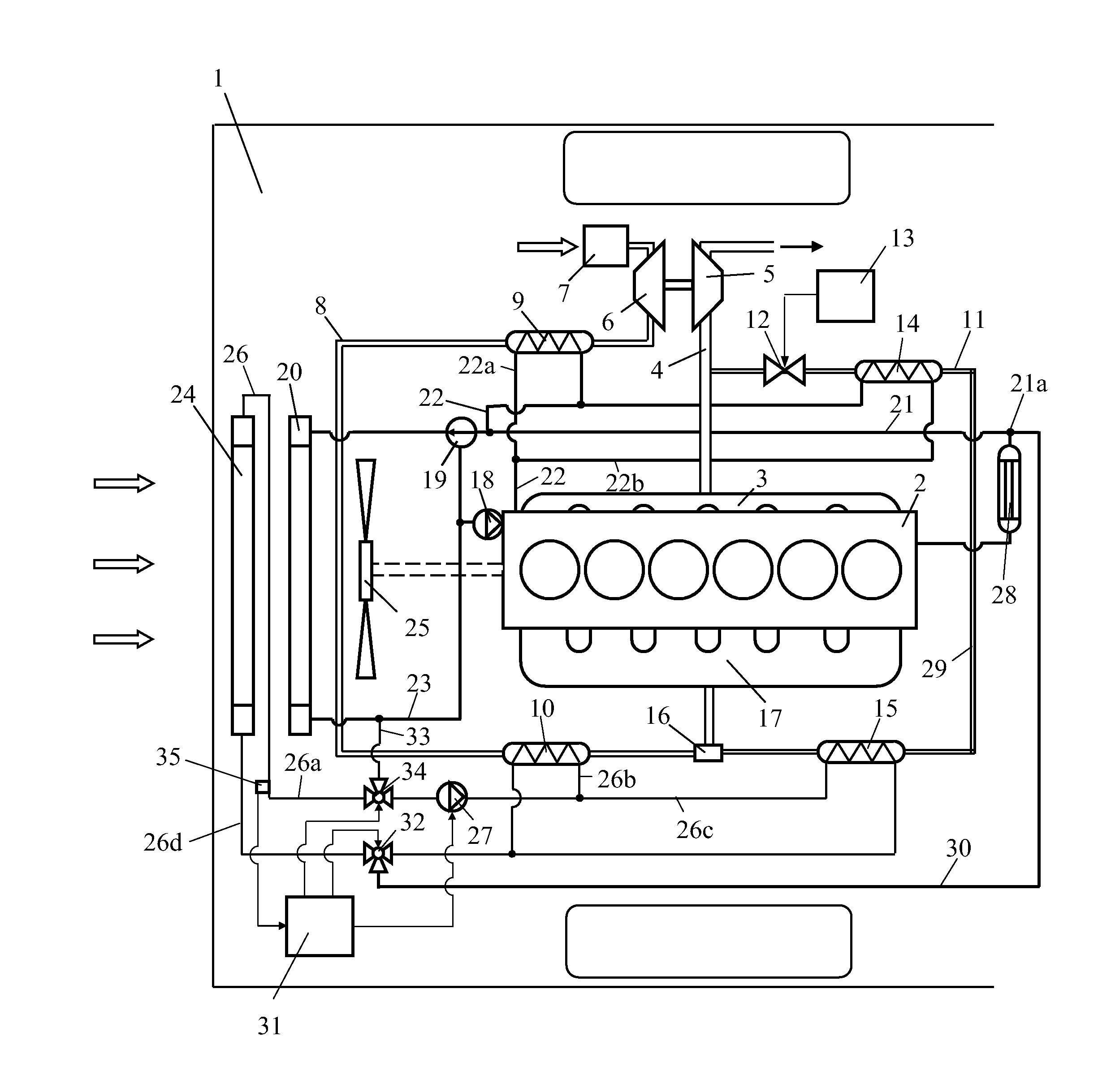
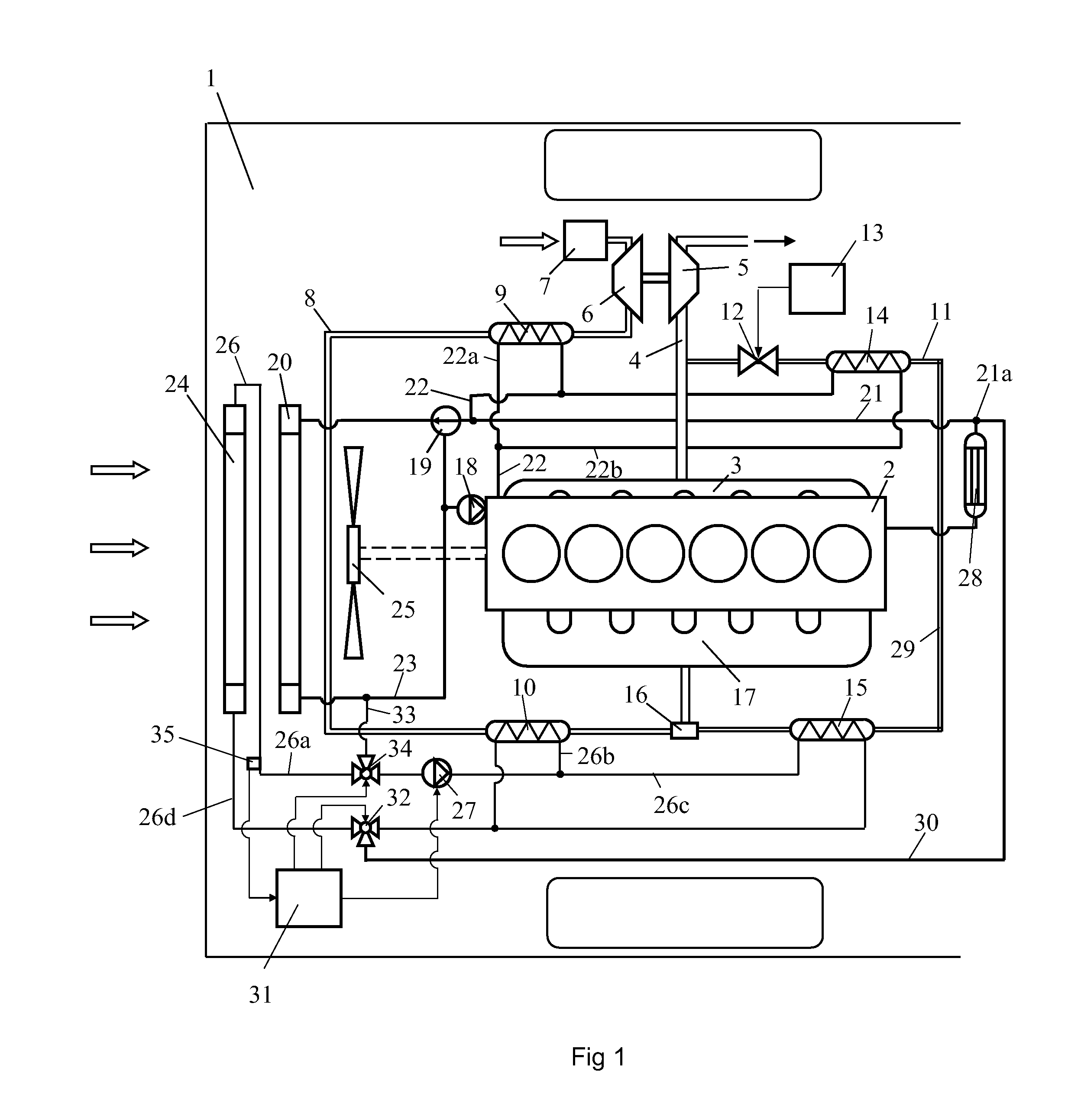
FIG. 1 depicts an arrangement for a supercharged combustion engine intended to power a schematically depicted vehicle 1. The combustion engine is here exemplified as a diesel engine 2. The diesel engine 2 may be used to power a heavy vehicle 1. The exhaust gases from the cylinders of the diesel engine 2 are led via an exhaust manifold 3 to an exhaust line 4. The diesel engine 2 is provided with a turbo unit which comprises a turbine 5 and a compressor 6. The exhaust gases in the exhaust line 4, which are at above atmospheric pressure, are led initially to the turbine 5. The turbine 5 is thus provided with driving power which is transferred, via a connection, to the compressor 6. The compressor 6 compresses air which is drawn into an air inlet line 8 via an air filter 7. The air in the inlet line 8 is cooled initially in a coolant-cooled first charge air cooler 9. The air is cooled in the first charge air cooler 9 by coolant from the combustion engine's cooling system. The compressed...


PUM


Abstract

An arrangement for a supercharged combustion engine (2) including a first cooling system with a circulating coolant, a second cooling system with a circulating coolant which is at a lower temperature than the coolant in the first cooling system, and a cooler (10, 15) in which a gaseous medium which contains water vapor is to be cooled by the coolant in the second cooling system. A first valve (32) which can be placed in a first position whereby it prevents coolant from the first cooling system from being led to the second cooling system via a first connecting line (30), and a second position whereby it allows warm coolant from the first cooling system to be led to the second cooling system via the first connecting line (30). The warm coolant from the first cooling system is intended to circulate at least a certain distance (26b, c) in the second cooling system so that it passes through the cooler (10, 15).

Description

BACKGROUND TO THE INVENTION, AND STATE OF THE ARTThe present invention relates to an arrangement for a supercharged combustion engine according to the preamble of claim 1.The amount of air which can be supplied to a supercharged combustion engine depends on the pressure of the air but also on the temperature of the air. Supplying the largest possible amount of air to the combustion engine entails effective cooling of the air before it is led to the combustion engine. The compressed air may be subjected to a first step of cooling in a charge air cooler which is cooled by coolant from the combustion engine's cooling system, and to a second step of cooling in a charge air cooler which is cooled by coolant from a cooling system in which the coolant is at a significantly lower temperature than in the combustion engine's cooling system. Such a low-temperature cooling system makes it possible for the compressed air to be cooled to a temperature close to the temperature of the surroundings....

Claims


Application Information

Patent Timeline
Patent Type & Authority Applications(United States)
IPC IPC(8): F02M25/07F02B29/04
CPCF01P7/165F01P2003/187F01P2005/105F01P2060/02F01P2060/06Y02T10/121F02B29/0443F02M25/0731F02M25/0732F01P11/20Y02T10/146F02B29/0412F02M26/24F02M26/28Y02T10/12F01P7/162
Inventor KARDOS, ZOLTANSODERBERG, ERIK
Owner SCANIA CV AB
Why Eureka
Try Eureka