
Cell module

a cell module and module technology, applied in the field of cell modules, can solve the problems of increasing the number of parts of the cell module, increasing the cost and weight, and requiring more cost and weigh

Inactive Publication Date: 2013-04-16
HITACHI AUTOMOTIVE SYST LTD
View PDF7 Cites 2 Cited by
  • Summary
  • Abstract
  • Description
  • Claims
  • Application Information

AI Technical Summary

Benefits of technology

The present invention aims to provide a cell module with safety and compact size. The invention achieves this by integrating the end cover and fixation portion, reducing the number of parts needed while maintaining safety. The bus bar plate may have protrusions or recesses to facilitate the end cover's attachment. A seal member may also be used to prevent gas leakage between the bus bar plate and the cell. Overall, the invention results in a cost-effective and lightweight cell module solution.

Problems solved by technology

Therefore, the number of parts of the cell module increases, as a result, the cost and weight increases.
Also, due to using a holder case for insuring cooling space and high strength in fixing the cell module to the vehicle, if making the number of the cell modules large to increase the power source device output, more cost and weight are required.
Consequently, its cost increases.

Method used


Image

  • Cell module
  • Cell module
  • Cell module

Examples


Embodiment Construction

[0025]An embodiment in accordance with the present invention applied to a cell module mounted on an automobile is explained below referring to the drawings.

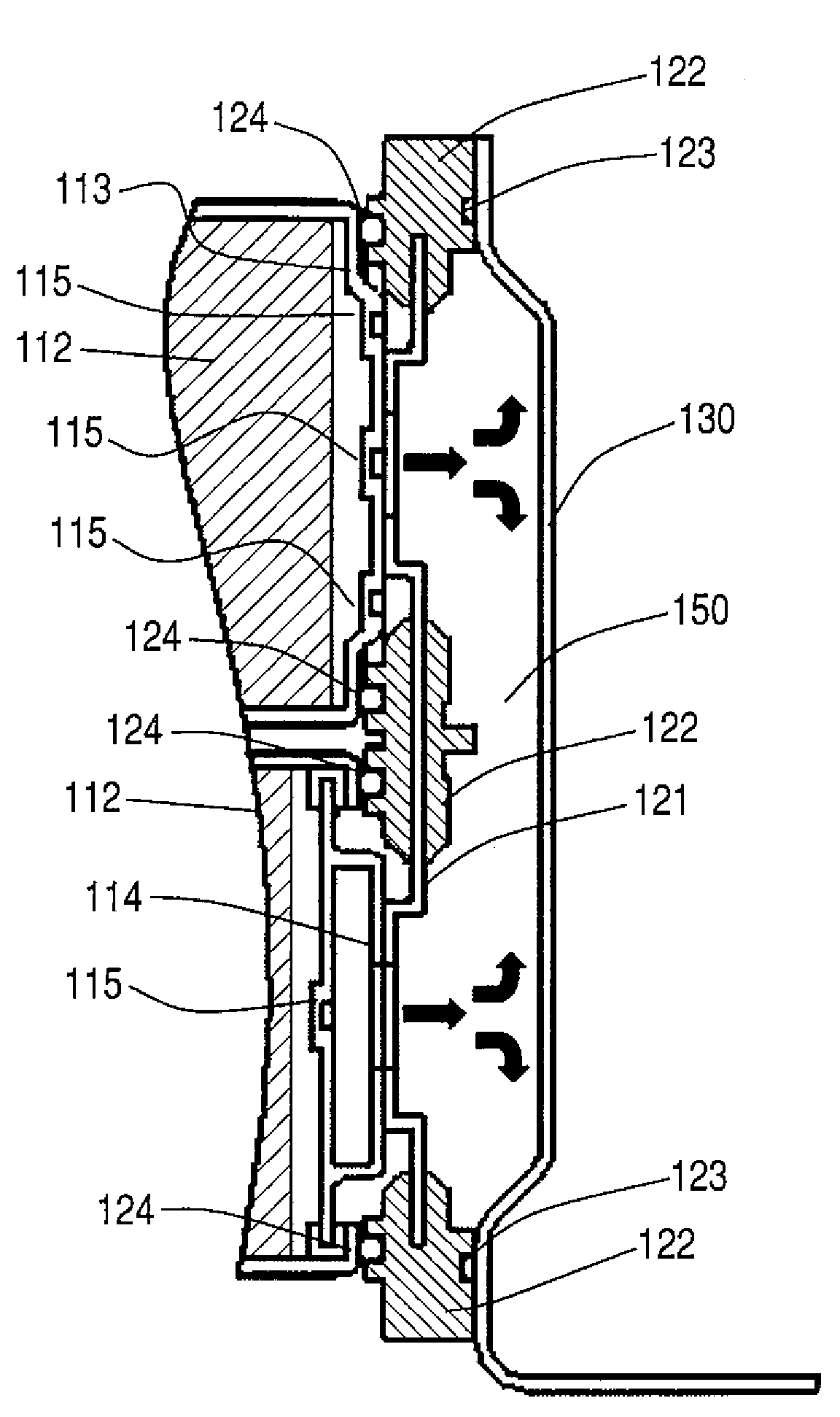
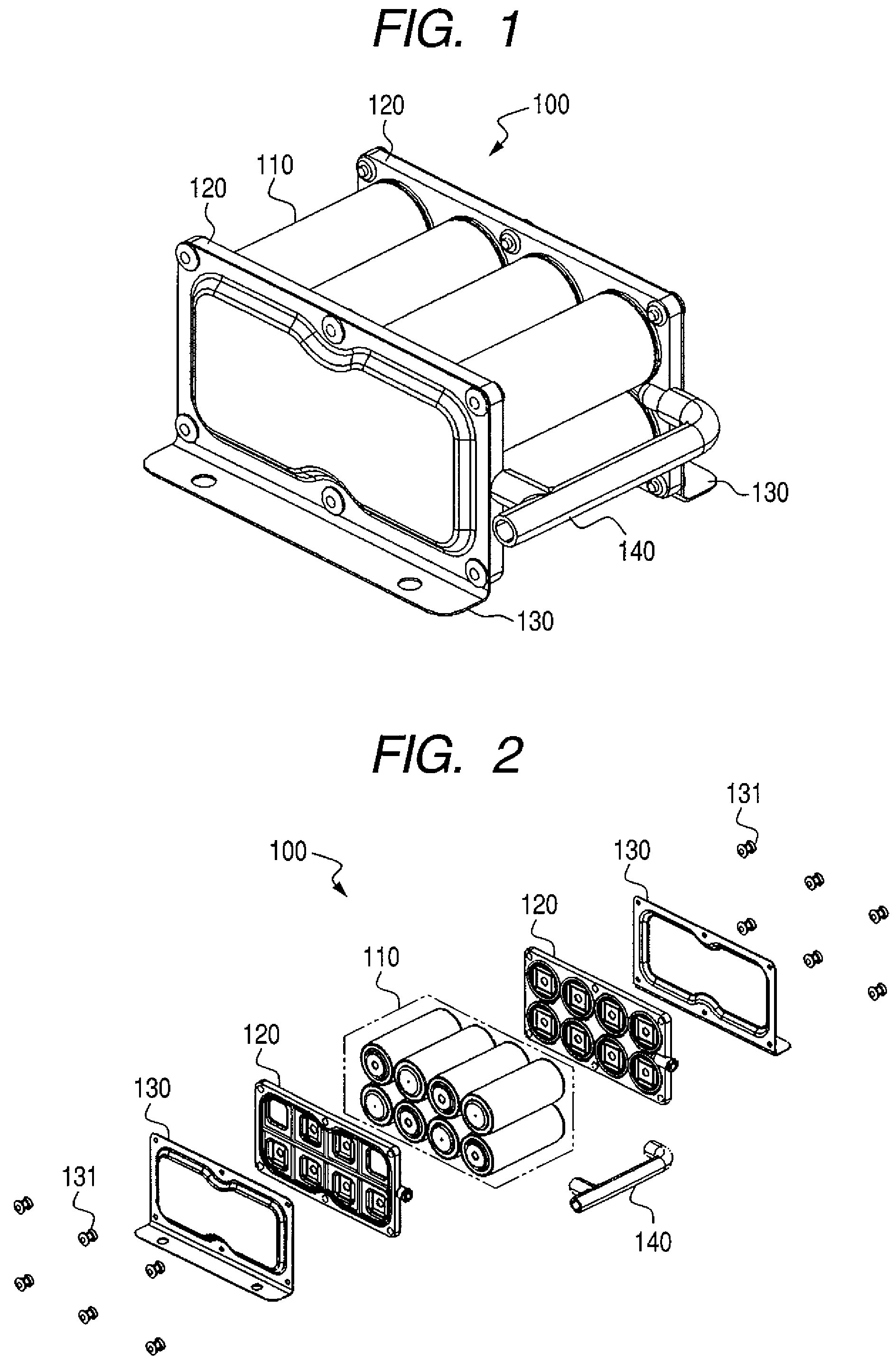
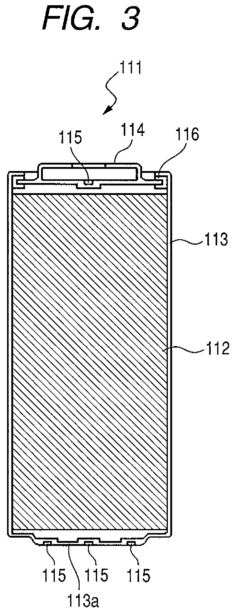
[0026]As shown in FIGS. 1 and 2, a cell module 100 of the present embodiment, classifying generally, is composed of a cell group 110 with a plurality of cells 111 (shown in FIG. 3), bus bar plates 120 including bus bars (shown in FIG. 4) connecting between cells 111 structuring the cell group 110, end covers 130 fixed to the bus bar plates 120 and a vehicle, and a gas discharge tube 140.

[0027]The cell group 110 is composed of a plurality of cells 111, for example, eight cells in the present embodiment and their different polarity terminal portions of the cells 111 are disposed in parallel and alternatively. These cells 111 are electrically connected in series via the bus bars 121. The cell is desirable to use a cylindrical lithium cell using lithium manganate or the like as its main structural material and being applied as power ...


PUM

PropertyMeasurementUnit
circumferenceaaaaaaaaaa
polarityaaaaaaaaaa
poweraaaaaaaaaa

Abstract

A cell module has a cell group with a plurality of cells connected to each other. The module comprises a bus bar plate including a bus bar connecting between the cells and an end cover for covering the bus bar plate. The cell module is configure to be fixed with the end cover.

Description

CLAIM OF PRIORITY[0001]This application claims priority from Japanese patent application serial No. 2008-003259, filed on Jan. 10, 2008, the content of which is hereby incorporated by reference into this application.BACKGROUND OF THE INVENTION[0002]The present invention relates to a cell module, particularly, to a cell module having a cell group with a plurality of cells connected to each other.[0003]Generally, a power source device has a cell module with many cells connected each other to obtain high power, and if necessary, more cell modules are further combined. For example, a power source device for vehicles adopts to combine many cell modules and mounts them on the vehicles.[0004]As an example described above, a technique is disclosed in a Japanese laid open patent publication No. 1998-270095, in which many cell modules with cells connected each other are attached to an end plate including a bus bar for conducting many cells connected each other, the end plate is fixed to a hol...

Claims


Application Information

Patent Timeline
Patent Type & Authority Patents(United States)
IPC IPC(8): H01M2/36H01M2/12H01M2/24H01M50/213H01M50/507H01M50/529
CPCH01M2/1077H01M2/1211H01M10/052Y02E60/10H01M50/308H01M50/507H01M50/213Y02P70/50
Inventor SATO, SEIICHI
Owner HITACHI AUTOMOTIVE SYST LTD
Learn More