Branch current monitor with calibration

a technology of bench current monitor and calibration, which is applied in the field of module meter, can solve the problems of calibration meter or inaccurate reading, field repairs, and modification of power meter or facility circuitry, and achieve the effect of avoiding calibration errors, avoiding calibration errors, and avoiding failure to calibrate meter or accept inaccurate readings

Active Publication Date: 2013-04-16
VERIS INDS
View PDF255 Cites 29 Cited by
  • Summary
  • Abstract
  • Description
  • Claims
  • Application Information

AI Technical Summary

Problems solved by technology

However, magnetization of the core of the transformer produces ratio and phase errors which may vary with the magnitude of the current being measured and the configuration of the particular transformer, including factors such as core material and turns ratio.
While initial installation of a power meter at the distribution panel is simplified by integrating a plurality of current transformers into a single assembly, field repairs, modifications and updating of the power meter or the facility's circuitry can be problematic.
As a result, it may be necessary to install a new, calibrated meter or accept inaccurate readings from a meter that has been altered by repair.

Method used


Image

  • Branch current monitor with calibration
  • Branch current monitor with calibration
  • Branch current monitor with calibration

Examples


Embodiment Construction

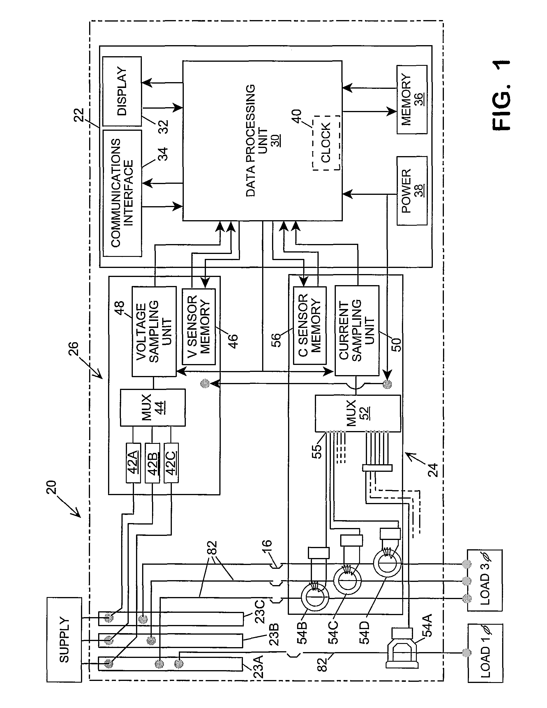
[0020]Referring in detail to the drawings where similar parts are identified by like reference numerals, and, more particularly to FIG. 1, a digital power meter 20 arranged to monitor the voltage and current in a plurality of branch circuits comprises, generally, a data processing module 22, a current module 24 and a voltage module 26. The data processing module 22 comprises a data processing unit 30 which, typically, comprises at least one microprocessor or digital signal processor (DSP). The data processing unit 30 reads and stores data received periodically from the voltage module and the current module, and uses that data to calculate the current, voltage, power and other electrical parameters that are the meter's output. The calculated values may be output to a display 32 for viewing at the meter or output to a communications interface 34 for transmission to another data processing system, such as a building management computer, for remote display or use in automating or managi...


PUM


Abstract

A meter for measuring electric power consumed by a plurality of branch circuits includes interchangeable current transformers including respective transformer memories for storage of transformer characterization data and enables self-discovery of a phase shift induced by respective current transformers and the phase of current conducted by each branch circuit.

Description

CROSS-REFERENCE TO RELATED APPLICATIONS[0001]This application claims the benefit of U.S. Provisional App. No. 61 / 199,912, filed Nov. 21, 2008.BACKGROUND OF THE INVENTION[0002]The present invention relates to a metering system and, more particularly, to a modular meter for measuring electricity consumption by a plurality of loads.[0003]The total power consumption of a building or other facility is monitored by the electric utility with a power meter located between the utility's distribution transformer and the facility's power distribution panel. However, in many instances it is desirable to sub-meter or attribute the facility's power usage and cost to different occupancies, buildings, departments, or cost centers within the facility or to monitor the power consumption of individual loads or groups of loads, such as motors, lighting, heating units, cooling units, machinery, etc. These single phase or multi-phase electrical loads are typically connected to one or more of the branch c...

Claims


Application Information

Patent Timeline
Patent Type & Authority Patents(United States)
IPC IPC(8): G01R15/18
CPCG01R21/133
Inventor BITSCH, MICHAELCOOK, MARTINRUPERT, MATTHEW
Owner VERIS INDS
Why Eureka
Try Eureka