
Combined impulsive and non-impulsive seismic sources

a seismic source and impulsive technology, applied in the field of marine seismic surveying, can solve the problems of large air gun chamber volume, inability to produce substantial seismic energy below about 8 hz, and inability to meet the requirements of a substantial increase in the size of the source of compressed air or gas,

Active Publication Date: 2013-04-23
PGS GEOPHYSICAL AS
View PDF26 Cites 50 Cited by
  • Summary
  • Abstract
  • Description
  • Claims
  • Application Information

AI Technical Summary

Benefits of technology

The invention has various benefits that are described in the text. Its technical effects include improved efficiency, improved performance, and improved overall quality. These benefits can be achieved by various methods and improvements that are introduced through the invention, such as optimizations in design, process, or materials used.

Problems solved by technology

As a practical matter, air gun arrays known in the art do not produce substantial seismic energy below about 8 Hz.
While it is possible to produce air gun arrays that would produce substantial seismic energy below 8 Hz, the chamber volume of air guns capable of producing such low frequency seismic energy would be so large as to require substantial increase in the size of the source of compressed air or gas, among other practical limitations.
The issue with this possibility is that airguns become much more unreliable at higher charge operating pressures.

Method used


Image

  • Combined impulsive and non-impulsive seismic sources
  • Combined impulsive and non-impulsive seismic sources
  • Combined impulsive and non-impulsive seismic sources

Examples


Embodiment Construction

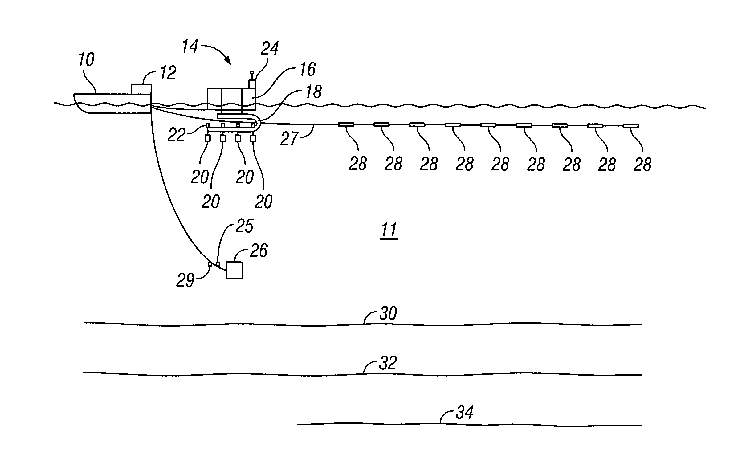
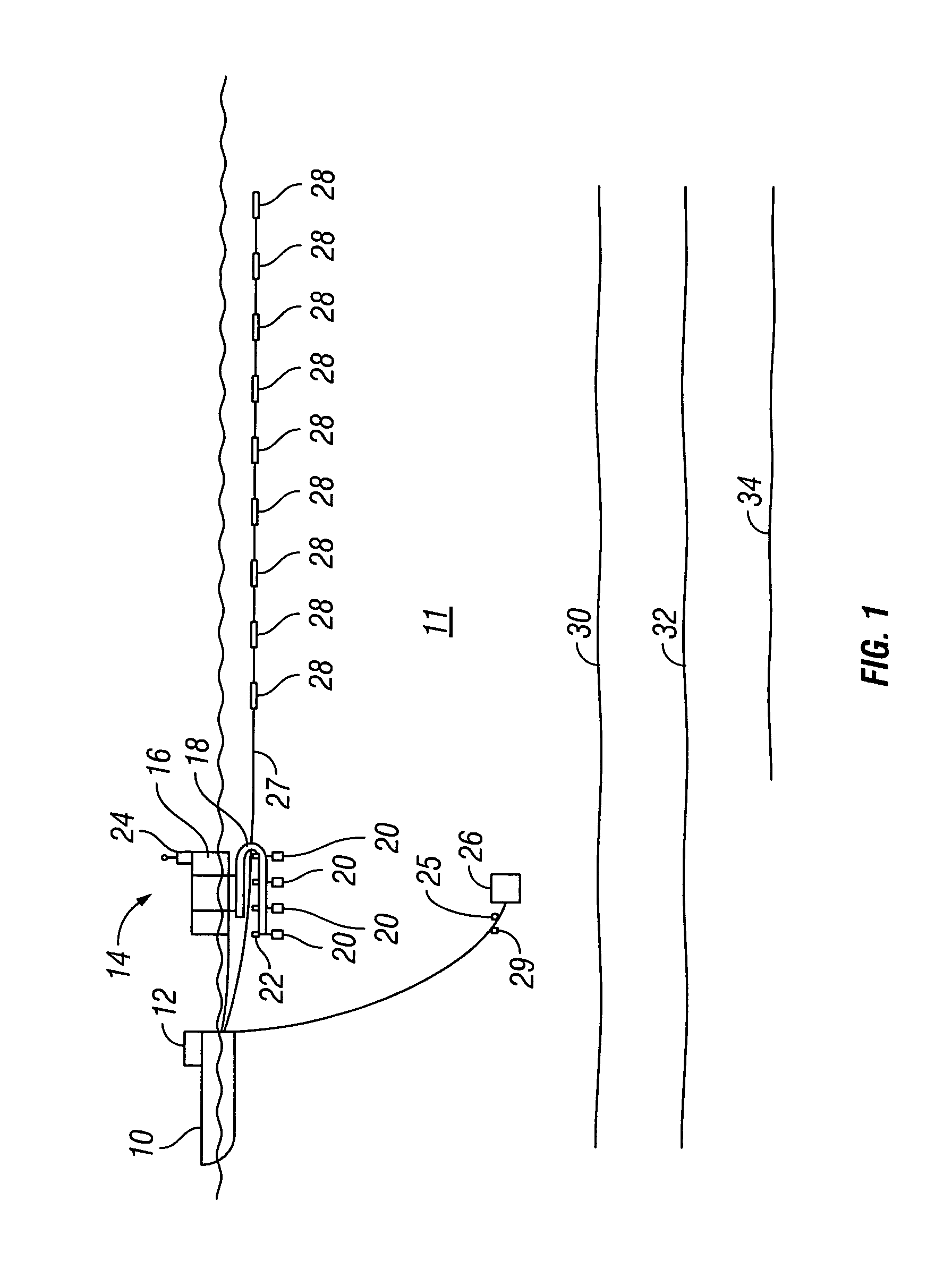
[0015]In the most general terms, a method according to the invention includes using an impulsive seismic energy source (a source that imparts substantially all its energy into the subsurface in a single, short duration event) in combination with a non-impulsive seismic energy source (wherein the energy of each actuation is spread over a relatively long time interval rather than in a single, short duration event). The combined impulsive and non-impulsive sources are used in combination so that relatively low amplitude seismic energy at low frequencies, e.g., below about 8 Hz, emitted by the impulsive source is supplemented by low frequency seismic energy from the non-impulsive source.

[0016]FIG. 1 shows a seismic acquisition system including an impulsive seismic energy source, which in the present example is an air gun array 14, and a non-impulsive seismic energy source, which in the present example is marine seismic vibrator 26. The system is deployed in a body of water 11 such as a ...


PUM


Abstract

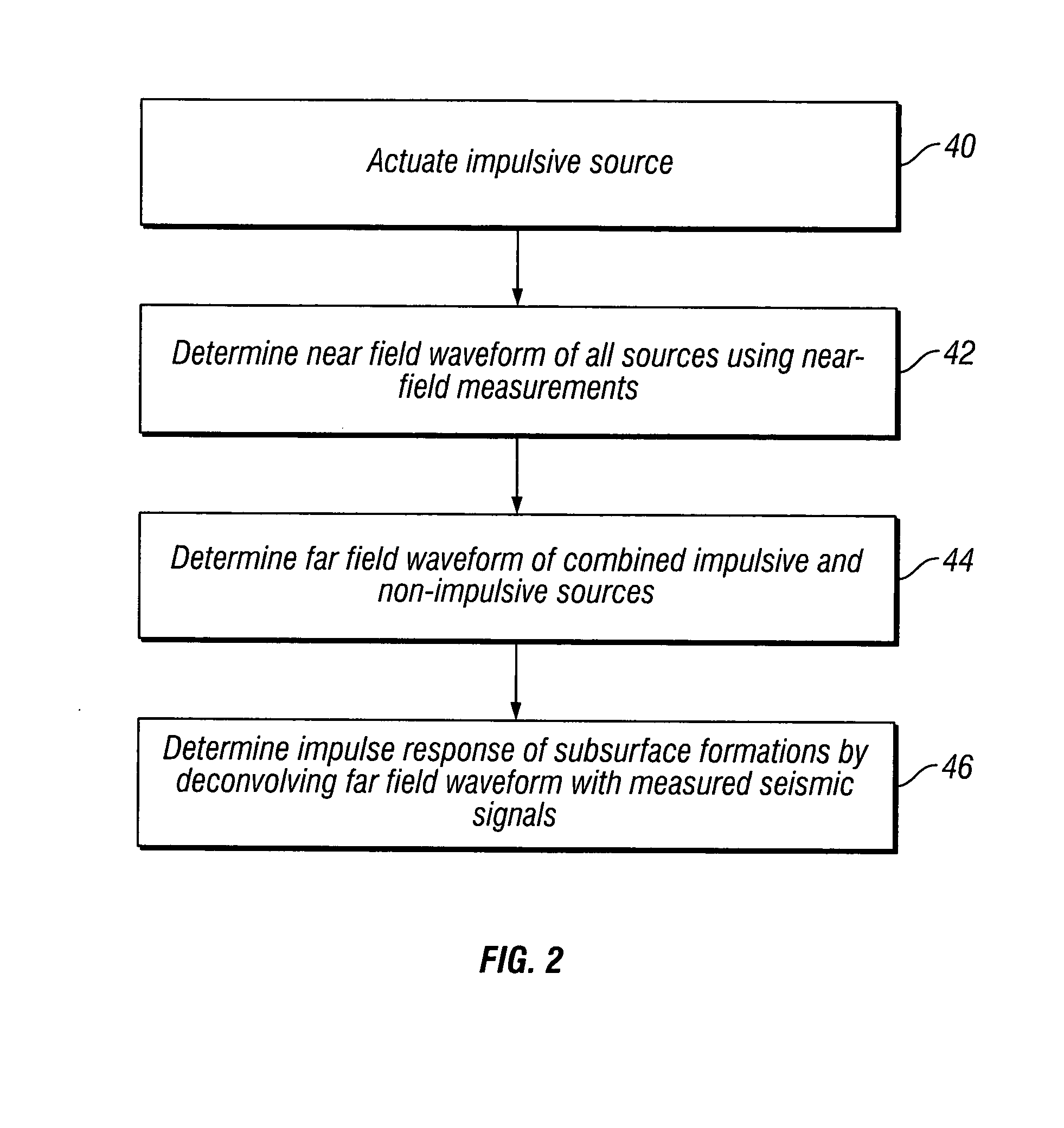
A method for seismic exploration of subsurface rock formations includes actuating an impulsive seismic energy source proximate the rock formations. A non-impulsive seismic energy source is actuated. A near field waveform of each of the impulsive and non-impulsive seismic energy sources is detected. A far field waveform of the combined output of the impulsive and non-impulsive seismic energy sources is determined from the near field waveforms. An impulse response of the subsurface rock formations is determined by deconvolving the far field waveform with detected seismic signals.

Description

CROSS-REFERENCE TO RELATED APPLICATIONS[0001]Not applicable.STATEMENT REGARDING FEDERALLY SPONSORED RESEARCH OR DEVELOPMENT[0002]Not applicable.BACKGROUND OF THE INVENTION[0003]1. Field of the Invention[0004]The invention relates generally to the field of marine seismic surveying. More specifically, the invention relates to seismic energy sources for marine surveying that have enhanced low frequency energy output.[0005]2. Background Art[0006]Marine seismic surveying includes deploying a seismic energy source in a body of water, actuating the source and detecting seismic energy reflected from acoustic impedance boundaries in rock formations below the water bottom. A typical seismic energy source used in marine seismic surveying is an air gun array. Air gun arrays include a plurality of individual air guns, each of which is connected to a source of compressed air or gas. Each air gun includes a chamber to store the compressed air or gas, at a selected pressure, and a remotely operable...

Claims


Application Information

Patent Timeline
Patent Type & Authority Patents(United States)
IPC IPC(8): G01V1/13
CPCG01V1/366G01H3/00
Inventor LUNDE, NILSZIOLKOWSKI, ANTONI MARJANPARKES, GREGORY ERNEST
Owner PGS GEOPHYSICAL AS
Learn More