Camera lens assembly and adaptation set

a technology for adapting sets and lenses, applied in the field of adapting sets for cameras, can solve problems such as limited interchangeability

Active Publication Date: 2013-04-30
CARL ZEISS SMT GMBH
View PDF14 Cites 0 Cited by
  • Summary
  • Abstract
  • Description
  • Claims
  • Application Information

AI Technical Summary

Benefits of technology

[0012]Also, less elasticity is present, because viewed in the direction of the optical axis, for example, a spring pre-tensioned bayonet catch can be replaced by a lens mount which is attachable to a camera mount by a threaded coupling. The flexural strength transversely to the optical axis is also increased by the small number of required components as compared to other adapter systems.
[0016]Advantageously, the camera lens or the adaption set includes one or more spacer discs, also called shims. These shims can be configured in the form of thin plastic foils or metal rings. For example, one or more shims are arranged between the contact surface of the focusing mount and the adapter ring. For example, if the adapter ring is fixed to the focusing mount via set-screws it is evident that the shim is provided with a number of apertures positioned correspondingly. The thickness of the shims can be just 1 / 100 mm in order to compensate for dimensional tolerances in the flange focal distance. In this way, optimum focusing of the optics of the focusing mount onto the image plane of the camera can be achieved.

Problems solved by technology

The disadvantage of this is that for geometrical reasons the known intermediate mounts only allow for very limited interchangeability.

Method used


Image

  • Camera lens assembly and adaptation set
  • Camera lens assembly and adaptation set
  • Camera lens assembly and adaptation set

Examples


Embodiment Construction

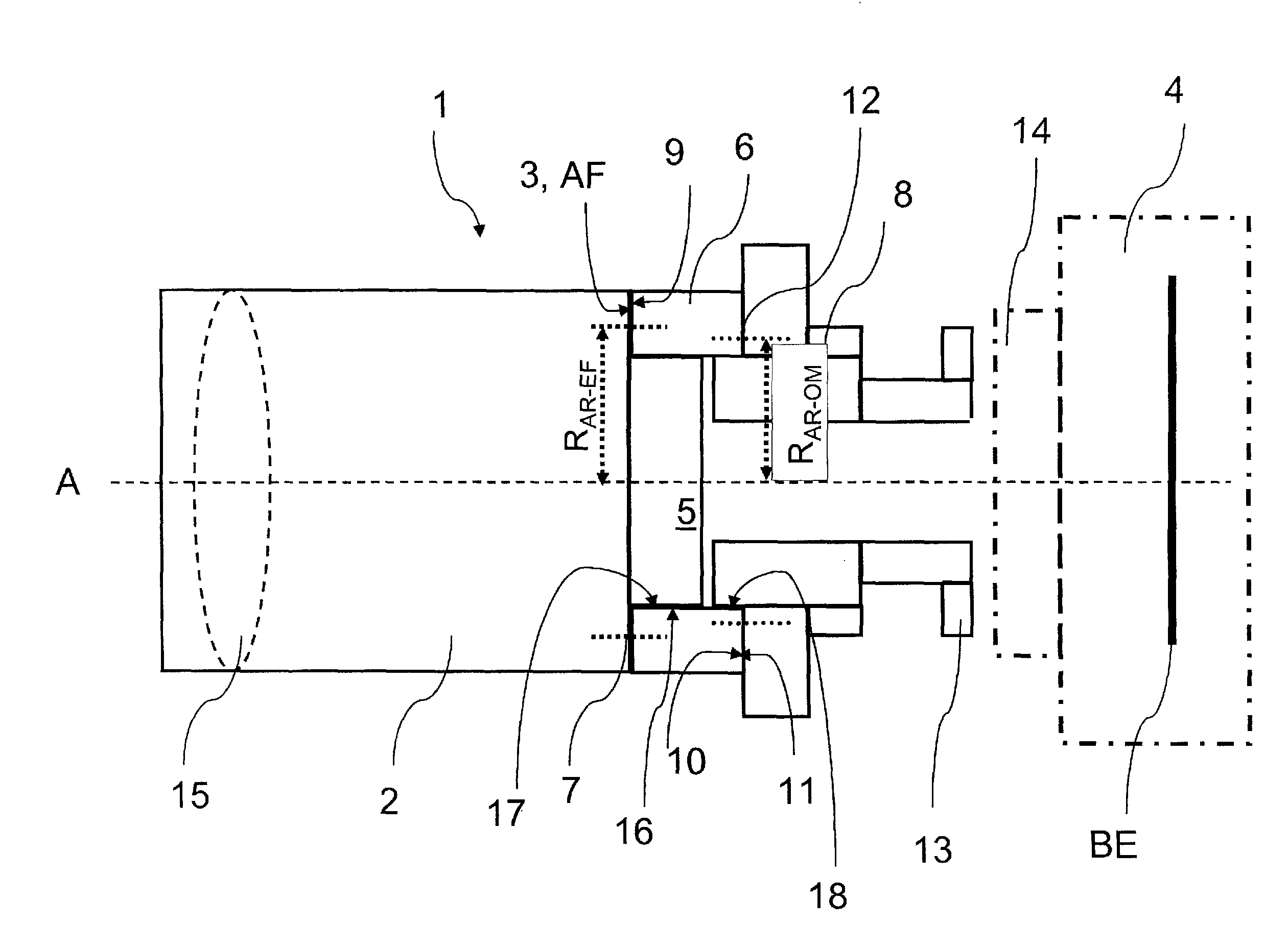
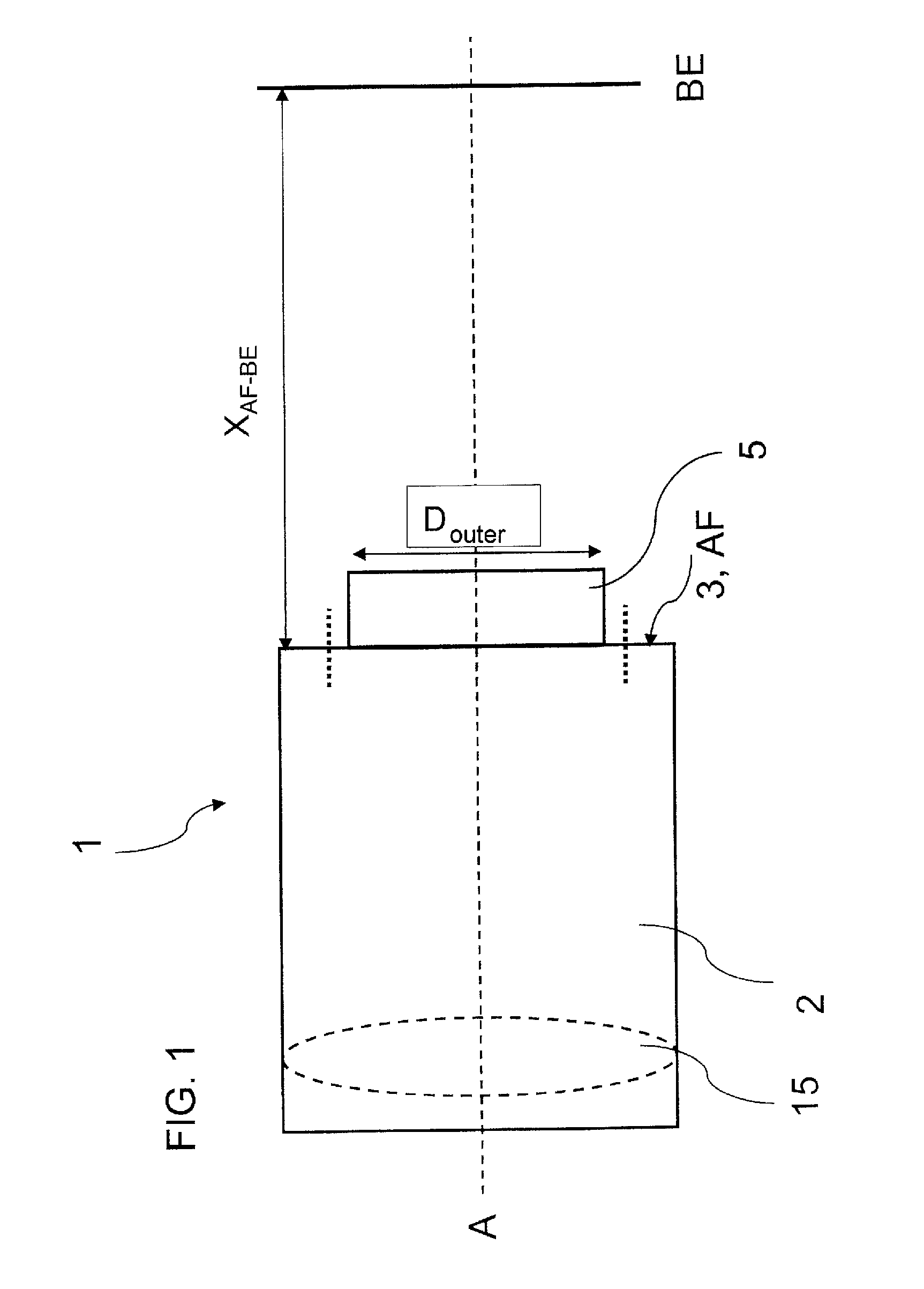
[0030]FIG. 1 shows a focusing mount 2 of a camera lens assembly 1. The focusing mount 2 is at a defined distance from a contact surface 3 of the focusing mount 2 on the camera side to the camera image plane BE of XAF-BE≧57.9 mm when the camera lens 1 is fixed to a camera 4.

[0031]Furthermore, the focusing mount 2 has a receiving lug 5 with an outer diameter of DAZ, outer≦52 mm for receiving an adapter ring 6.

[0032]Furthermore, the focusing mount 2 has optical elements which are arranged in the focusing mount and define an optical axis A. At least one of the optical elements can be moved along the optical axis A via at least one focusing ring, not shown. As an example, an optical element 15, here a lens, is shown in dotted lines.

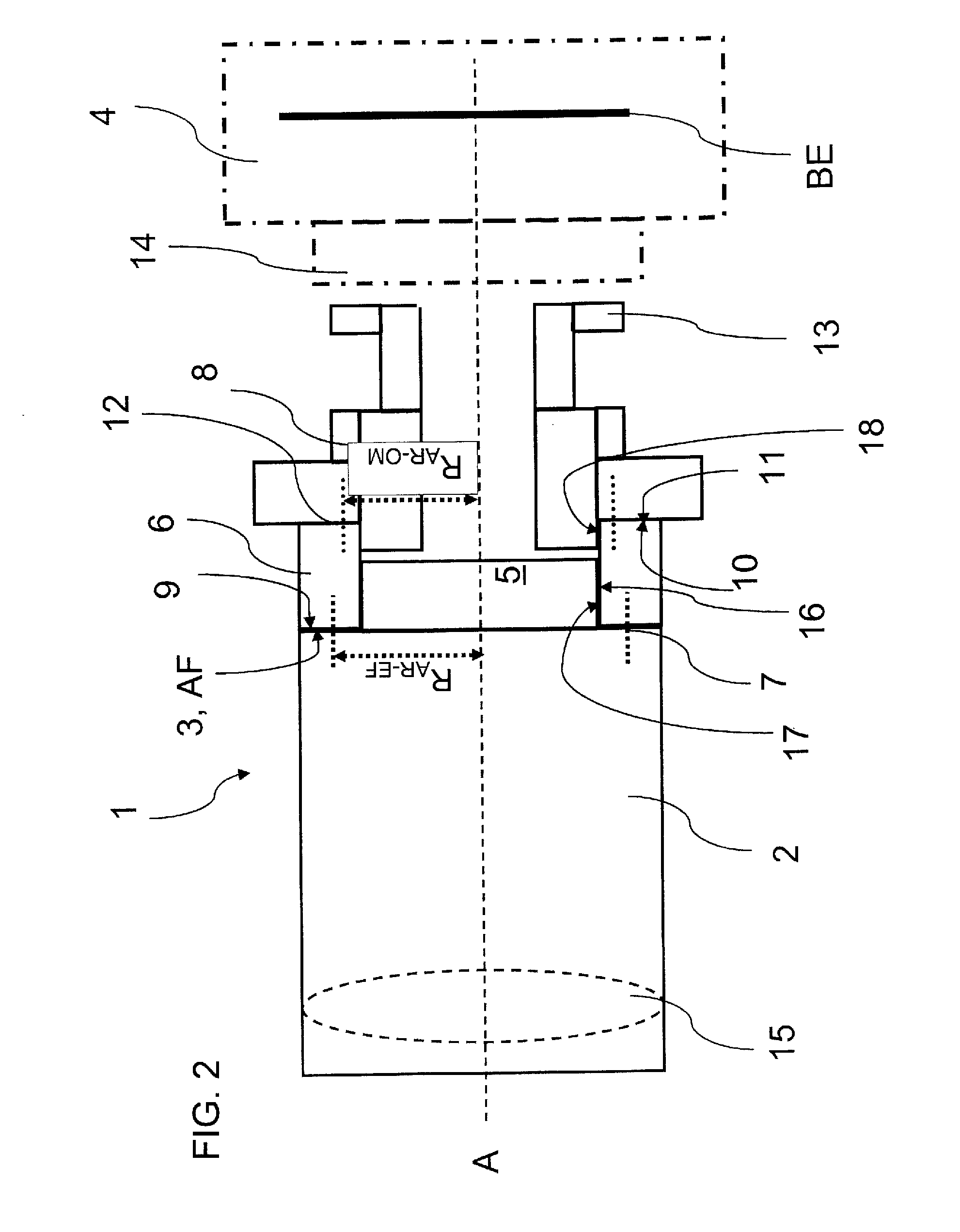
[0033]The dimensions are chosen such that a PL-mount can be attached directly on the focusing mount 2 in order to form a camera lens 1 therewith. An adapter ring 6 is provided so that other mounts can also be attached. This is shown in FIG. 2.

[0034]The adapter...


PUM


Abstract

A camera lens assembly includes a focusing mount having a receiving lug and optical elements, which are arranged in the focusing mount, and define an optical axis. An adapter ring has a first planar surface and a second planar surface which are parallel to each other. The first planar surface is in contact engagement against a camera-side contact surface of the focus mount and the second planar surface is in contact with a lens-side contact surface of a lens mount. The lens mount has a tubular-shaped lens mount socket and lens mount attachment elements which are configured to coact with the camera mount attachment elements of a camera.

Description

CROSS REFERENCE TO RELATED APPLICATION[0001]This application claims priority of U.S. provisional application Ser. No. 61 / 282,847, filed Apr. 9, 2010, and the entire content of the above application is incorporated herein by reference.BACKGROUND OF THE INVENTION[0002]A mount is understood as a connection device between a camera and the focusing mount of a lens. A mount includes a first part, the camera mount, and a second part, the lens mount. For example, the connection device can be configured as a connecting thread or a bayonet catch. Known mounts are, for example, the C-Mount, CS-Mount, PL-Mount, EF-Mount, F-Mount, K-Mount, and Alpha-Mount.[0003]It is generally known that lenses for cameras, especially film cameras, comprise a focusing mount and assembled lens mount and are available as such in the marketplace. A particular lens mount can only be combined with a specific camera mount. If a user has cameras having different mounts, the user must purchase suitable lenses for each c...

Claims


Application Information

Patent Timeline
Patent Type & Authority Patents(United States)
IPC IPC(8): G03B17/00
CPCG03B17/02G03B17/12G03B17/14
Inventor WEBER, UWESEHR, HOLGERLENHOF, HELMUT
Owner CARL ZEISS SMT GMBH
Why Eureka
Try Eureka