Interspinous spinal prosthesis

a spinal prosthesis and interspinal nerve technology, applied in the field of interspinal nerve prosthesis, can solve the problems of unsatisfactory mechanically and delicate solutions, and achieve the effect of variable stiffness

Inactive Publication Date: 2010-02-04
KYPHON
View PDF99 Cites 6 Cited by
  • Summary
  • Abstract
  • Description
  • Claims
  • Application Information

AI Technical Summary

Benefits of technology

[0022]Moreover, the materials required for each segment of this assembly thus formed may differ, thereby forming a composite assembly with variable stiffness.

Problems solved by technology

This requirement is, however, problematic between the fifth lumbar vertebra (L5) and the first sacral vertebra (S1) because the S1 spinous process very often protrudes very little (agenesis) and therefore cannot constitute a stable bearing point.
Due to the specific biomechanics of the lumbo-sacral joint, all of these solutions are both delicate to implant and unsatisfactory from a mechanical standpoint.
However, degenerative pathologies affect several consecutive vertebral joints or evolve such that they affect several consecutive vertebral joints.
Documents FR 2 623 085, WO 2005 / 110258, WO 2006 / 086241 and FR 2 828 398 describe various types of interspinous implants, but which do not provide a satisfactory solution to the aforementioned problem of providing an implant for which migration or forward or rear sliding is prevented, which remaining relatively easy to implant and providing satisfaction from a mechanical standpoint.

Method used


Image

  • Interspinous spinal prosthesis
  • Interspinous spinal prosthesis

Examples


Embodiment Construction

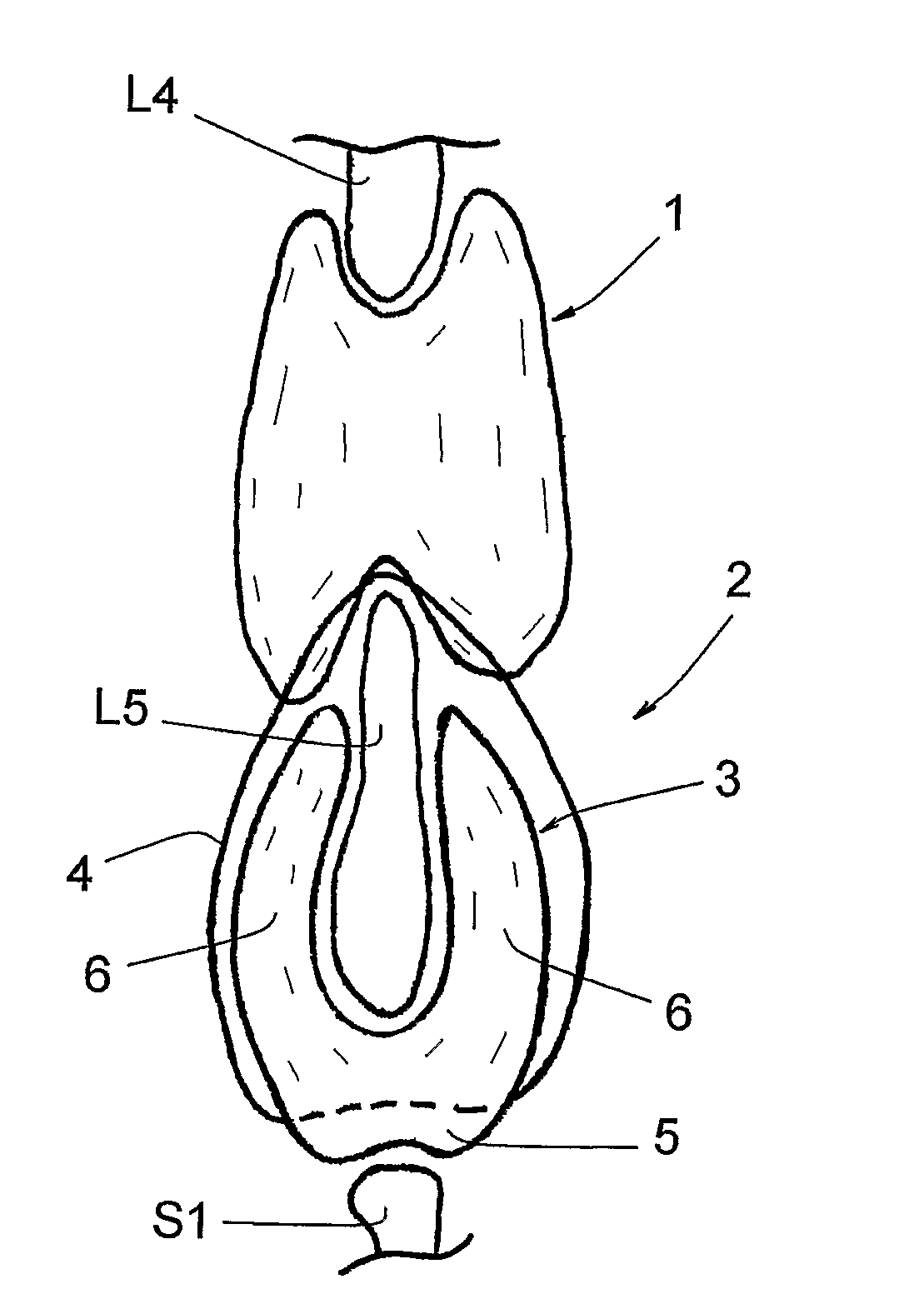
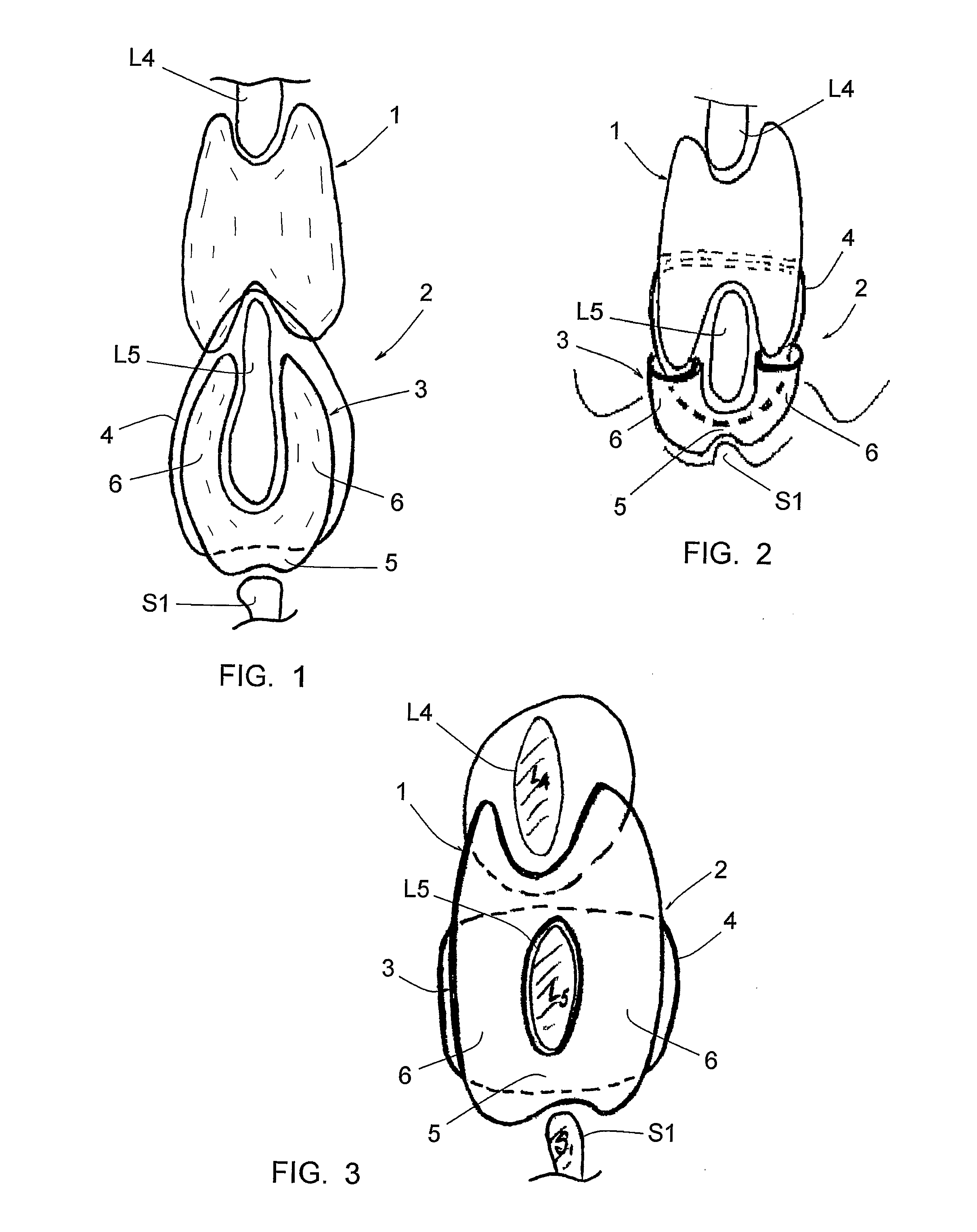
[0027]FIG. 1, annexed, shows three successive spinous processes, generally L4, L5 and S1. Between the L4 and L5 spinous processes is placed an interspinous implant 1, in particular that known under the name “DIAM”.

[0028]The prosthesis 2 according to the invention comprises an implant 3 and a link 4.

[0029]The implant 3 has a U-shape, meaning it comprises an intermediate portion 5 and two side portions 6. At least the intermediate portion 5 is shock absorbing. This implant 3 is intended to envelope the spinous process of L5, said intermediate portion 5 being intended to be engaged between this spinous process and the S1 spinous process.

[0030]The link 4 goes through said intermediate portion 5 and forms two side strands which can go alongside said side portions 6 and be connected to each other so as to closely stick said intermediate portion 5 against the lower edge of the L5 spinous process.

[0031]FIG. 2 shows a variation of this embodiment wherein the free ends of the side portions 6 ...


PUM


Abstract

This spinal prosthesis (2) comprises:—a U-shaped implant (3), comprising an intermediate portion (5) and two side portions (6), at least the intermediate portion (5) being shock absorbing; this implant (3) is intended to envelope the spinous process of a first vertebra (L5), said intermediate portion (5) being intended to be engaged between this spinous process and an area of a second vertebra (S1), underlying; and—a link (4) crossing through the intermediate portion (5) and forming two side strands which are able to go along-side or cross said side portions (6) and to be connected to each other so as to closely stick said intermediate portion (5) against the lower edge of the spinous process of said first vertebra (L5).

Description

[0001]The present invention relates to an interspinous spinal prosthesis.STATE OF THE ART[0002]Interspinous spinal prostheses have been developed as an alternative to interpedicular osteosynthesis devices. The interspinous gap, thus maintained, provides a certain degree of stability by reducing the play between the posterior rims of the vertebrae.[0003]It is essential for this type of implant to conform to the morphology of the spinous processes to prevent migration or forward or rear sliding. This requirement is, however, problematic between the fifth lumbar vertebra (L5) and the first sacral vertebra (S1) because the S1 spinous process very often protrudes very little (agenesis) and therefore cannot constitute a stable bearing point.[0004]The solutions imagined to date have tried to use bearing on the sacrum, either through hooks incorporated in the device and bearing on the upper edge of the sacrum, or using side attachments or transverse links fastened by screws going through th...

Claims


Application Information

Patent Timeline
Patent Type & Authority Applications(United States)
IPC IPC(8): A61B17/70
CPCA61B17/7062
Inventor TAYLOR, JEAN
Owner KYPHON
Why Eureka
Try Eureka