Electrostatic clutch

Active Publication Date: 2017-08-03
CARNEGIE MELLON UNIV
View PDF0 Cites 13 Cited by
  • Summary
  • Abstract
  • Description
  • Claims
  • Application Information

AI Technical Summary

Benefits of technology

[0012]In an alternative example, three electrodes are arranged in a parallel orientation. One electrode is attached to a body of a device and a second electrode is connected to an output supplying a force. A third electrode is connected to a spring and placed between the first and second electrodes. The electrode connected to the spring can be engaged against either the body electrode or the output electrode. In this configuration, the spring can be stretched by the output force, affixed to the frame to store the energy, then later returned to the output to perform work, forming a type of energy recycling actuator. Given the micron-scale thickness of the electrodes, the actuator can be comprised of tens to hundreds of clutch/spring

Problems solved by technology

Like a capacitor, power consumption is very low once a charge is devel

Method used


Image

  • Electrostatic clutch
  • Electrostatic clutch
  • Electrostatic clutch

Examples


Embodiment Construction

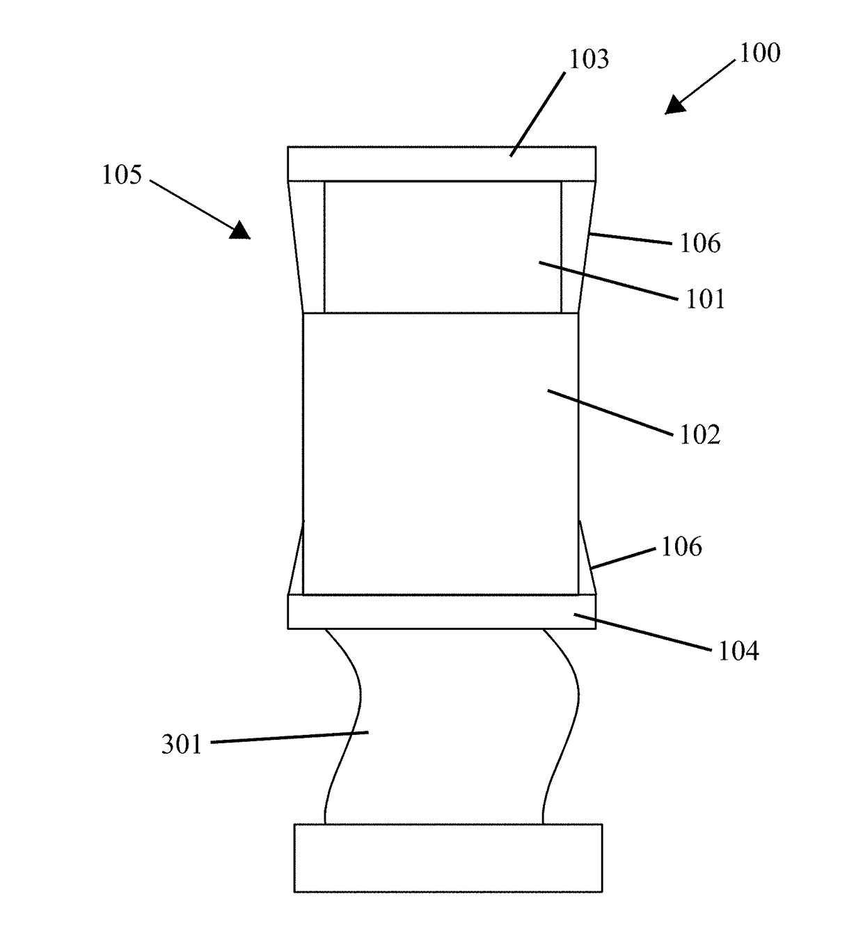
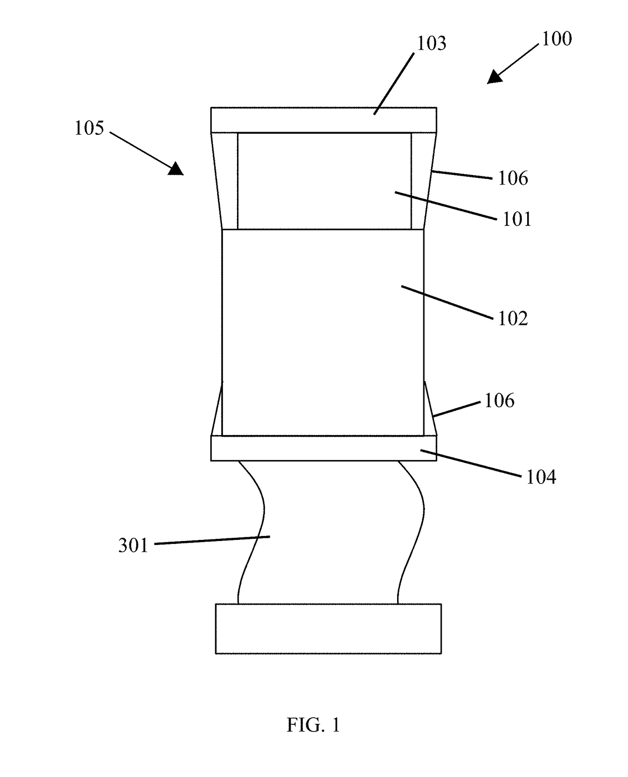
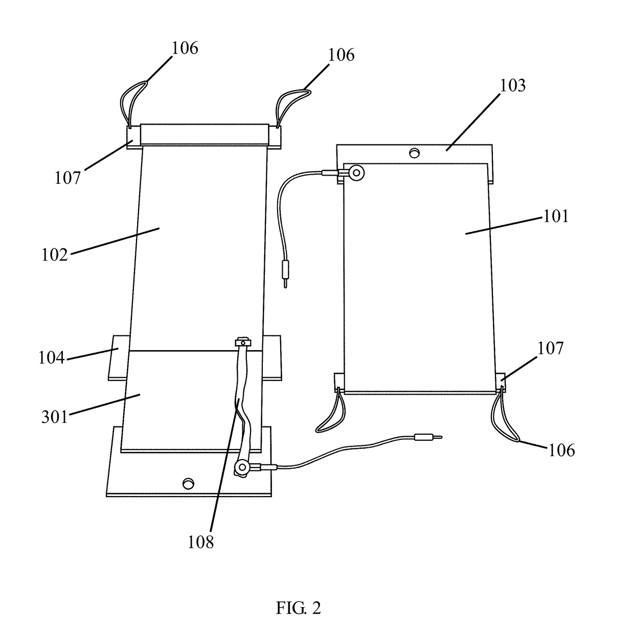
[0028]Embodiments of the present invention and its advantages are best understood by referring to the figures. FIG. 1 shows the clutch 100 of the present invention according to one example embodiment. As shown in FIG. 1, the clutch 100 is comprised of a first electrode 101 and a second electrode 102. The electrodes 101, 102 are aligned in a parallel orientation so that a surface of the first electrode 101 overlaps a surface of the second electrode 102. The conductive surfaces 202 do not contact as they are separated by a layer of dielectric material 203 deposited on one or both of the electrodes 101, 102. In this example embodiment, only one electrode 101, 102 is coated with a layer of dielectric material 203 to minimize the distance between the electrodes 101, 102.

[0029]A frame 103 is attached to one end of the first electrode 101 and a separate frame 104 is attached to one end of the second electrode 102. The frames 103, 104 are positioned at opposite ends of the clutch 100, as sh...


PUM


Abstract

An electrostatic clutch is described comprising a plurality of micron-scale thickness electrodes, adjacent electrodes being separated by a thin film of dielectric material. A power source and controller apply a voltage across two electrodes, causing an electrostatic force to develop. When engaged, a force can be transferred through the clutch. A tensioning device maintains the alignment of the clutch when the electrodes are disengaged, but permits movement in at least one direction. In some embodiments, multiple clutches are connected to an output to provide variable force control and a broad range of torque input and output values. Moreover, the clutch can be used as an energy-recycling actuator that captures mechanical energy from negative work movements, and returns energy during positive work movements.

Description

CROSS-REFERENCE TO RELATED APPLICATIONS[0001]This application claims the benefit under 35 U.S.C. §§119-120 of Provisional Serial No. 62 / 495,693, filed Sep. 21, 2016 and PCT Application No. PCT / US2015 / 055005, filed Oct. 9, 2015, which claims priority to Provisional Ser. No. 62 / 122,066, filed Oct. 9, 2014, and Provisional Ser. No. 62 / 231,818, filed Jul. 16, 2015, all of which are incorporated herein by reference.STATEMENT REGARDING FEDERALLY SPONSORED RESEARCH[0002]This invention was made with government support under NSF Grant No. IIS-1355716. The government has certain rights in this invention.BACKGROUND OF THE INVENTION[0003]The invention relates generally to an electrostatic clutch. More specifically, the invention relates to a lightweight and high power density electrostatic clutch that can be incorporated into robotic systems, including exoskeletons and wearable devices, among other uses.[0004]Clutches have many uses in mechanical systems, often being used to improve the functio...

Claims


Application Information

Patent Timeline
IPC IPC(8): H02N13/00
CPCH02N13/00F16D27/00F16D28/00
Inventor MAJIDI, CARMELCOLLINS, STEVENDILLER, STUART
Owner CARNEGIE MELLON UNIV
Why Eureka
Try Eureka