Electromagnetic flow meter

a flow meter and electromagnet technology, applied in the direction of liquid/fluent solid measurement, instruments, machines/engines, etc., can solve the problems of abnormal state of the electromagnet flow meter b, 1/b>, and difficulty in accurately measuring the flow rate, so as to prevent output hunting, accurate and rapid detection of non-full levels of fluids

Inactive Publication Date: 2013-04-30
YOKOGAWA ELECTRIC CORP
View PDF13 Cites 0 Cited by
  • Summary
  • Abstract
  • Description
  • Claims
  • Application Information

AI Technical Summary

Benefits of technology

[0036]An object of the invention provides a two-frequency-excitation-type electromagnetic flow meter capable of accurately and rapidly detecting the non-full level of a fluid to be measured and preventing output hunting due to the detection of the non-full level.

Problems solved by technology

When the fluid is at the non-full level, the electromagnetic flow meter 1 is in an abnormal state in which it is difficult to accurately measure the flow rate.
(1) In the method of making a constant current flow, when the AC coupling circuit is used, the following problems arise. When the fluid is changed from the full level to the non-full level or from the non-full level to the full level, the outputs of the electrodes 12 and 13 vary greatly.
Therefore, it takes a long time to detect the full level and the non-full level (for example, about 10 minutes).
Therefore, it is difficult for the non-full level detecting unit 54 to detect the non-full level.

Method used


Image

  • Electromagnetic flow meter
  • Electromagnetic flow meter
  • Electromagnetic flow meter

Examples


first embodiment

(First Embodiment)

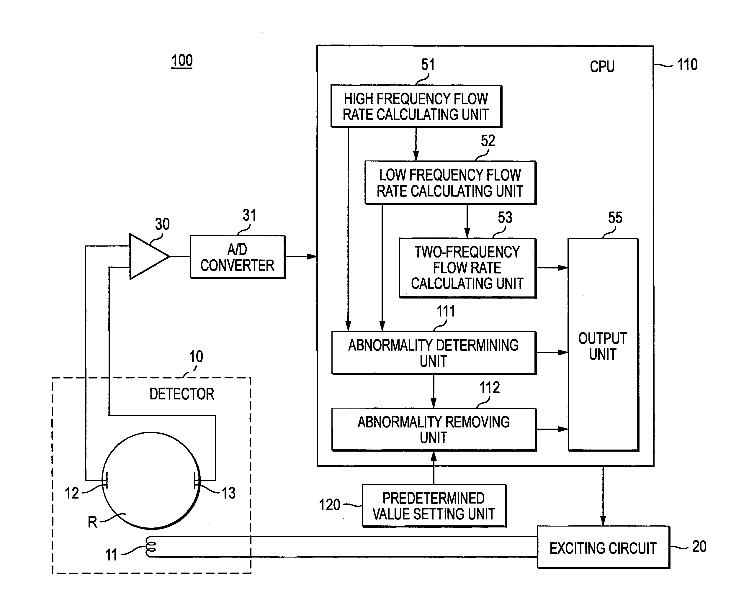
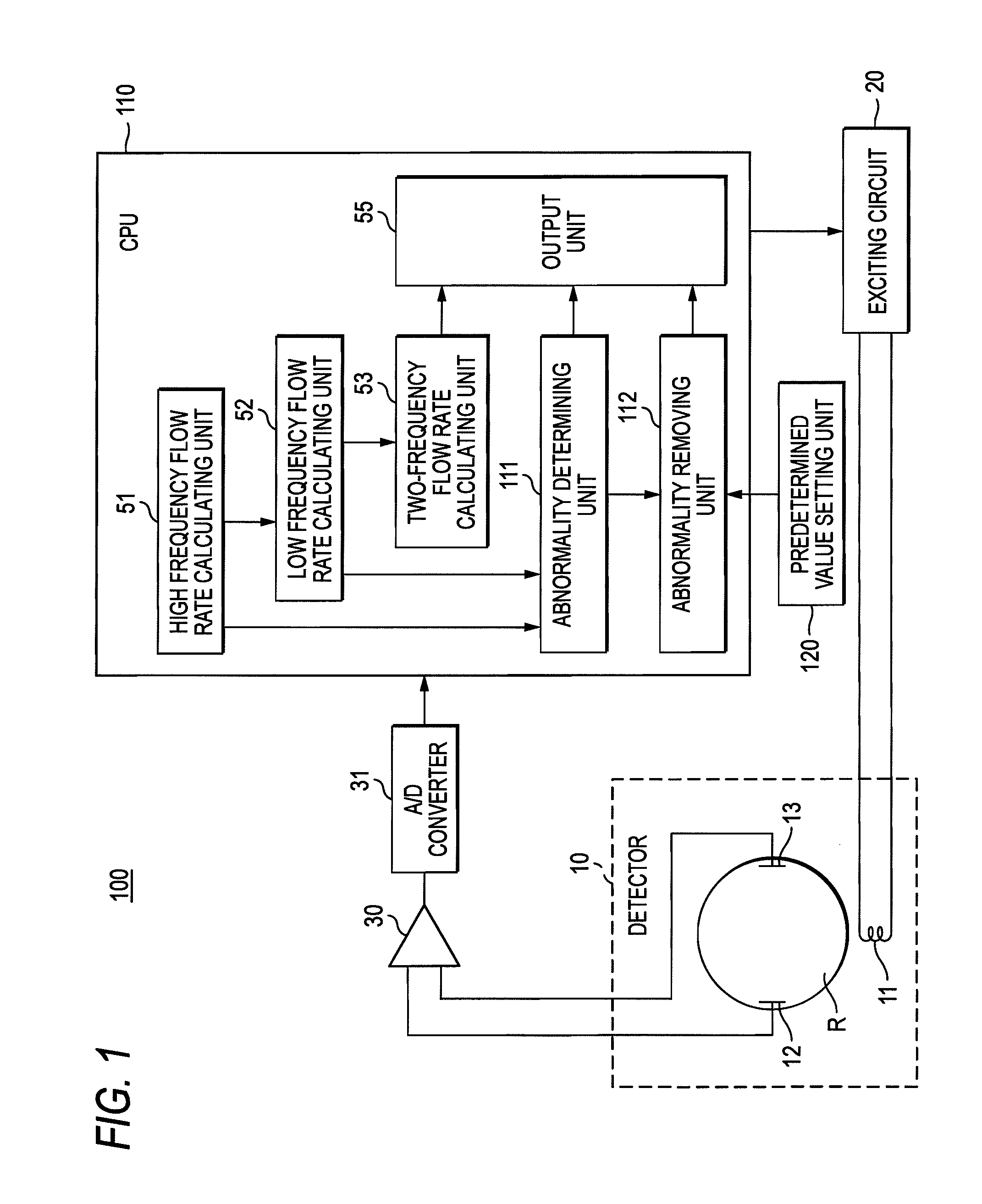
[0065]FIG. 1 is a diagram illustrating the structure of an electromagnetic flow meter 100 according to an embodiment of the invention. In FIG. 1, the same components as those shown in FIG. 8 are denoted by the same reference numerals and a description thereof will be omitted.

[0066]In FIG. 1, the electromagnetic flow meter 100 differs from the electromagnetic flow meter shown in FIG. 8 in that it includes a predetermined value setting unit 120 and a CPU 110 includes an abnormality detecting unit 111 and an abnormality removing unit 112 instead of the non-full level detecting unit 54 (see FIG. 8).

[0067]The abnormality detecting unit 111 receives flow rates from a high frequency flow rate calculating unit 51 and a low frequency flow rate calculating unit 52 and determines whether a fluid is in an abnormal state, such as at a non-full level.

[0068]The abnormality removing unit 112 receives the determination result from the abnormality detecting unit 111 and the flow rat...

second embodiment

(Second Embodiment)

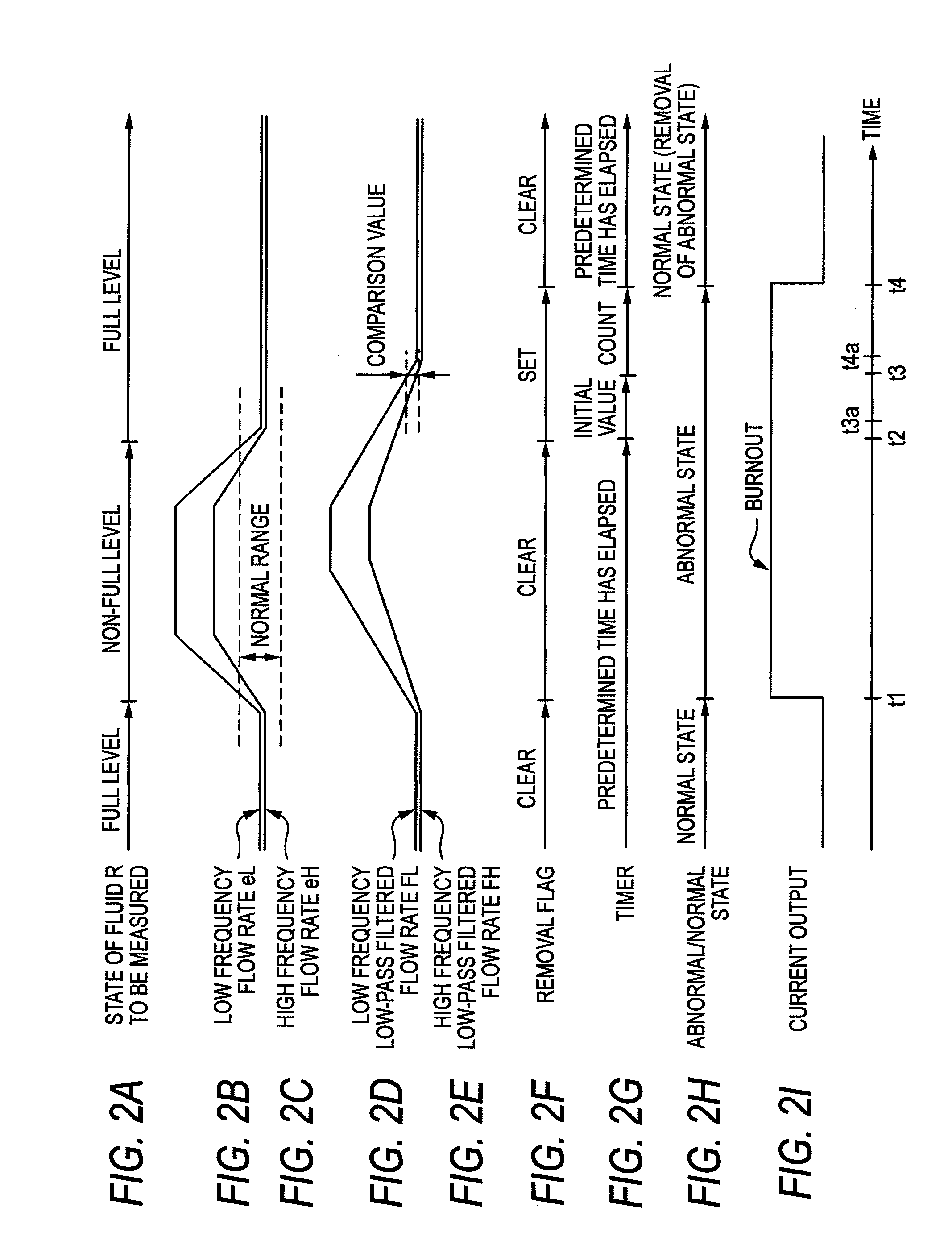
[0111]In FIGS. 2A to 2I, at the non-full level, when the difference between the low frequency low-pass filtered flow rate FL(d) and the high frequency low-pass filtered flow rate FH(e) is excessively large or when a time constant used for the low-pass filtering is excessively large, it takes a long time for the difference between the low frequency low-pass filtered flow rate FL(d) and the high frequency low-pass filtered flow rate FH(e) to be less than the comparison value.

[0112]That is, the period from the time t2 to the time t3 is increased. As a result, the time until the abnormal state is removed at the time t4 is increased. This embodiment is for significantly reducing the time.

[0113]The second embodiment when the difference between the low frequency low-pass filtered flow rate FL and the high frequency low-pass filtered flow rate FH is excessively large will be described with reference to FIG. 4. FIG. 4 is a diagram illustrating the structure of an electroma...


PUM


Abstract

There is provided an electromagnetic flow meter that applies magnetic fields with a first frequency and a second frequency, to a fluid to be measured, calculates a first flow rate, calculates a second flow rate, performs low-pass filtering on the first flow rate to calculate a first low-pass filtered flow rate, and performs low-pass filtering on the second flow rate to calculate a second low-pass filtered flow rate, the electromagnetic flow meter including: an abnormality detecting unit that detects an abnormal state in which, the fluid is at non-full level on the basis of at least one of the first flow rate and the second flow rate; and an abnormality removing unit that removes the abnormal state on the basis of the first low-pass filtered flow rate and the second low-pass filtered flow rate, when the abnormality detecting unit does not determine that the fluid is in the abnormal state.

Description

CROSS-REFERENCE TO RELATED APPLICATION[0001]This application is based on and claims priority under 35 U.S.C. §119 from Japanese Patent Application No. 2009-129229 filed on May 28, 2009.BACKGROUND OF THE INVENTION[0002]1. Technical Field[0003]The present invention relates to an electromagnetic flow meter, and more particularly, to a two-frequency-excitation-type electromagnetic flow meter that detects the non-full level of a fluid to be measured.[0004]2. Description of the Related Art[0005]In flow control performed in chemical plants, as the excitation type of an electromagnetic flow meter that is used to measure the flow rate of a fluid, generally, a composite excitation type (hereinafter, a ‘two-frequency excitation type’) has been known in which an excitation current component with a high frequency (first frequency) and an excitation current component with a frequency (second frequency) lower than the first frequency flow through an exciting coil at the same time to form a composi...

Claims


Application Information

Patent Timeline
Patent Type & Authority Patents(United States)
IPC IPC(8): G01F1/60
CPCG01F1/60G01F25/0007G01F25/10
Inventor SUGAWARA, FUJIKAZUSHIMURA, TOORU
Owner YOKOGAWA ELECTRIC CORP
Why Eureka
Try Eureka