Vehicle brake device for electronic hydraulic brake system

a brake system and electronic technology, applied in the direction of braking systems, rotary clutches, fluid couplings, etc., can solve the problems of ehb system not being able to takes a long time to block fluid, and can not quickly form braking pressure, so as to achieve quick form a great braking pressure and less pedal force

Active Publication Date: 2013-05-07
HL MANDO CORP
View PDF12 Cites 5 Cited by
  • Summary
  • Abstract
  • Description
  • Claims
  • Application Information

AI Technical Summary

Benefits of technology

[0009]Accordingly it is an aspect of the present invention to provide a vehicle brake device of an electronic hydraulic brake system, capable of completely separating an input shaft of a pedal from a piston of a master cylinder in a normal operation mode, and quickly forming a great braking pressure with less pedal force in an abnormal operation mode.
[0016]As described above, a vehicle brake device of an electronic hydraulic brake system according to the present invention can completely separate an input shaft coupled with a brake pedal from a first piston of a master cylinder in a normal operation mode, and quickly form a great braking pressure with less pedal force in an abnormal operation mode.

Problems solved by technology

However, according to the braking device of the EHB system, in the abnormal operation mode, it takes a long time to block the fluid introduced into the simulation piston by using the piston which is moved forward in the master cylinder as the pressure is applied to the brake pedal by the driver.
That is, it takes a long time to form the braking pressure by the pedal force of the driver, so that, the EHB system cannot quickly form the braking pressure.

Method used


Image

  • Vehicle brake device for electronic hydraulic brake system
  • Vehicle brake device for electronic hydraulic brake system
  • Vehicle brake device for electronic hydraulic brake system

Examples


Embodiment Construction

[0022]Reference will now be made in detail to the embodiments of the present invention, examples of which are illustrated in the accompanying drawings, wherein like reference numerals refer to the like elements throughout. The embodiments are described below to explain the present invention by referring to the figures.

[0023]Hereinafter, a preferred embodiment of a vehicle brake device for an electronic hydraulic brake (EHB) system according to the present invention will be described with reference to accompanying drawings.

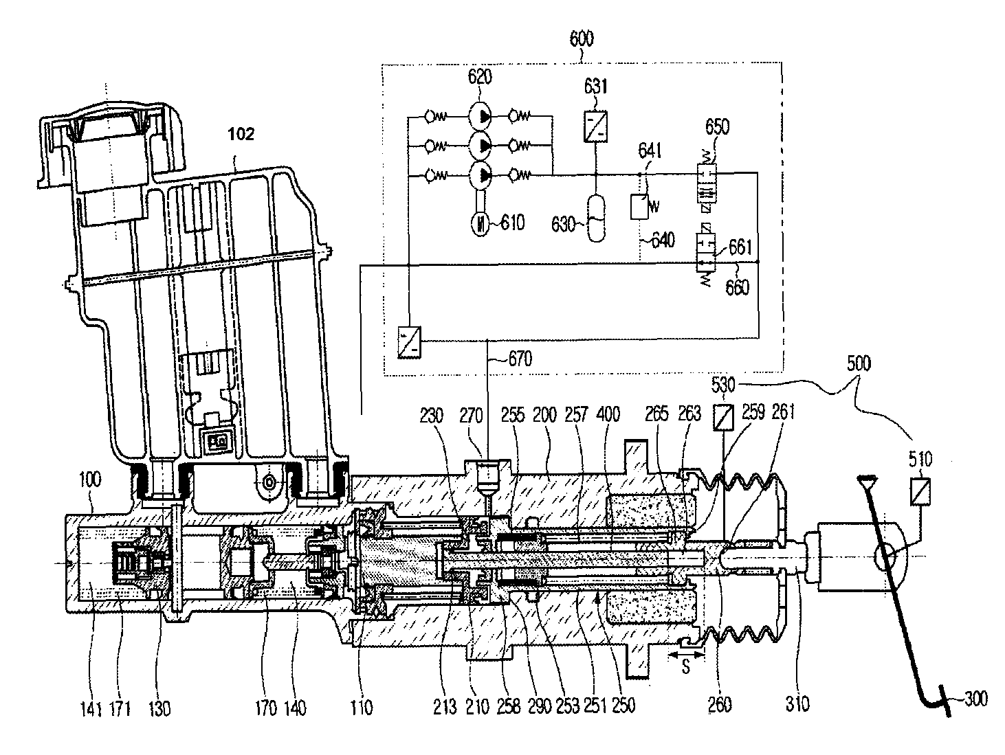
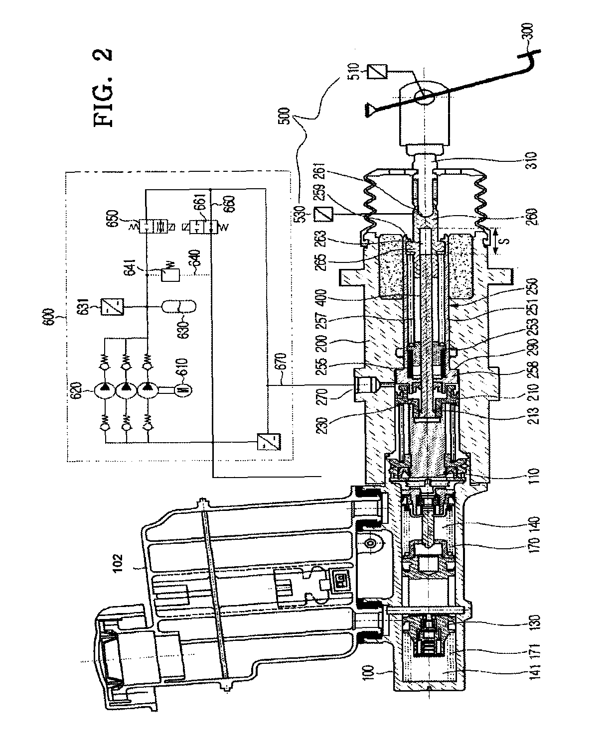
[0024]As shown in FIG. 2, the vehicle brake device for the electronic hydraulic brake (EHB) system according to the present invention includes an input shaft 310, a pedal operation detector 500, a pedal simulator 250, a master cylinder 100, a reservoir 102, a control piston 210, a control chamber 230, a hydraulic pressure supply 600, and an anti-lock brake system (ABS) hydraulic pressure part 700. The input shaft 310 is coupled to a brake pedal 300 manipulated by a...


PUM


Abstract

A vehicle brake device includes an input shaft coupled to a brake pedal, a pedal operation detector, a pedal simulator coupled to the input shaft in a control housing, a master cylinder, a control piston, a control chamber, and a hydraulic pressure supply, wherein the pedal simulator includes a pedal simulator piston, a pressing member, a simulator piston provided in the pedal simulator piston, and a push rod which is accommodated in the pressing member while being spaced apart from a bottom wall of a guide groove by passing through the pedal simulator piston and the simulator piston from the control piston to the input shaft, and wherein a diameter of the master cylinder is greater than a diameter of the simulator piston, and a diameter of the control piston is greater than a diameter of the master cylinder.

Description

CROSS-REFERENCE TO RELATED APPLICATION[0001]This application claims the benefit of Korean Patent Application No. 10-2008-0002990 filed on Jan. 10, 2008, in the Korean Intellectual Property Office, the disclosure of which is incorporated herein by reference.BACKGROUND OF THE INVENTION[0002]1. Field of the Invention[0003]The present invention relates to a vehicle brake device for an electronic hydraulic brake (EHB) system. More particularly, the present invention relates to a vehicle brake device an electronic hydraulic brake (EHB) system, capable of quickly forming a braking pressure according to pedal force of a driver in an abnormal operation mode of an EHB system, and suitable for generating a greater braking pressure under the same pedal force.[0004]2. Description of the Related Art[0005]In general, if a driver steps on a brake pedal in a normal operation mode, an electronic hydraulic brake (EHB) system detects the displacement of the brake pedal by a displacement sensor to close...

Claims


Application Information

Patent Timeline
Patent Type & Authority Patents(United States)
IPC IPC(8): B60T8/34B60T13/18
CPCB60T7/042B60T8/4077B60T8/409B60T13/167B60T8/88B60T8/00
Inventor YANG, I JIN
Owner HL MANDO CORP
Why Eureka
Try Eureka