Current driving method and circuit for controlled driving of light-emitting diodes

a technology of light-emitting diodes and current driving, applied in the direction of electric variable regulation, process and machine control, instruments, etc., can solve the problems of complete working and audible whistle, and achieve the effect of avoiding thermal damag

Active Publication Date: 2013-05-07
ZETEX SEMICON PLC
View PDF12 Cites 1 Cited by
  • Summary
  • Abstract
  • Description
  • Claims
  • Application Information

AI Technical Summary

Benefits of technology

[0006]It is an object of certain embodiments to provide load driving methods and circuits which obviate or mitigate at least one of the problems associated with the prior art. Certain embodiments aim to provide drive methods and circuits able to drive a regulated current through a load despite varying supply voltage, load temperature, and PCB temperature. Certain embodiments aim to provide LED drive methods and circuits. Certain embodiments aim to provide drive methods and circuits able to provide control of the magnitude of regulated load current. Certain embodiments aim to provide LED drive methods and circuits in which LED brightness can be adjusted (for example by adjusting LED current between 10% and 100% of a nominal maximum value). Certain embodiments aim to provide load driving methods and circuits able to monitor load temperature and provide protection to avoid thermal damage. Certain embodiments aim to provide load driving methods and circuits capable of working with wider supply ranges than the prior art, for example supply voltages from 1.2V to 18V (to work from a single cell up to an automotive supply voltage).
[0031]Thus, as the switching device is switched off when the monitoring signal reaches the predetermined threshold, increased capacitor voltage reduces the switch current at which this takes place, and vice versa.
[0034]The temperature monitoring current may then be arranged to charge the same capacitor used to integrate the difference between the load and demand currents. Advantageously, this results in inductor peak current being reduced as load temperature increases (e.g. above a predetermined upper temperature threshold), thereby providing protection from thermal damage. In other words, the temperature signal is used to reduce inductor-charging current to provide protection.
[0037]In certain embodiments the control means is arranged to determine the delay time according to the demand signal. This is in contrast to prior art arrangements in which the “off” time was fixed, and provides the advantage that off time can be lengthened in response to reduced demand, so enabling “off” times to be longer than would otherwise be the case. The increased “off” time, together with the continuously variable peak coil current, enable the device to have a wide power output range and thus operate continuously at the extremes of the power settings In turn, this enables switching frequencies to be kept out of the audible range, to avoid whistling.
[0038]Thus, in certain embodiments the demand signal is a voltage signal having a magnitude indicative of the desired current, and the control means is arranged to increase the delay time in response to a decrease in the demand signal magnitude. Conveniently, this can be achieved by arranging the demand signal to drive a monostable circuit, a smaller demand signal taking longer to charge the monostable timing capacitor to the required switching voltage.
[0073]Again, this provides the advantage that delay time can be altered according to demand signal (e.g. lengthened in response to reduced demand) which, in conjunction with the continuously variable peak coil current, keeps switching frequencies out of the audible range and so avoids whistling.

Problems solved by technology

However, a disadvantage with such known circuits operating in skip (start-stop) mode is that they can produce relatively large ripple, with the resultant emission of electromagnetic radiation, and furthermore the frequency of the skipping can be within the audio range, resulting in the coil core emitting an audible whistle, which in many applications (such as the driving of LEDs in a torch) is undesirable.
If this power is excessive, the only way the device can control it is to stop working completely until the output voltage or current is within the desired range.
This slow on and off cycling results in an audible whistle from the inductor.

Method used


Image

  • Current driving method and circuit for controlled driving of light-emitting diodes
  • Current driving method and circuit for controlled driving of light-emitting diodes
  • Current driving method and circuit for controlled driving of light-emitting diodes

Examples


Embodiment Construction

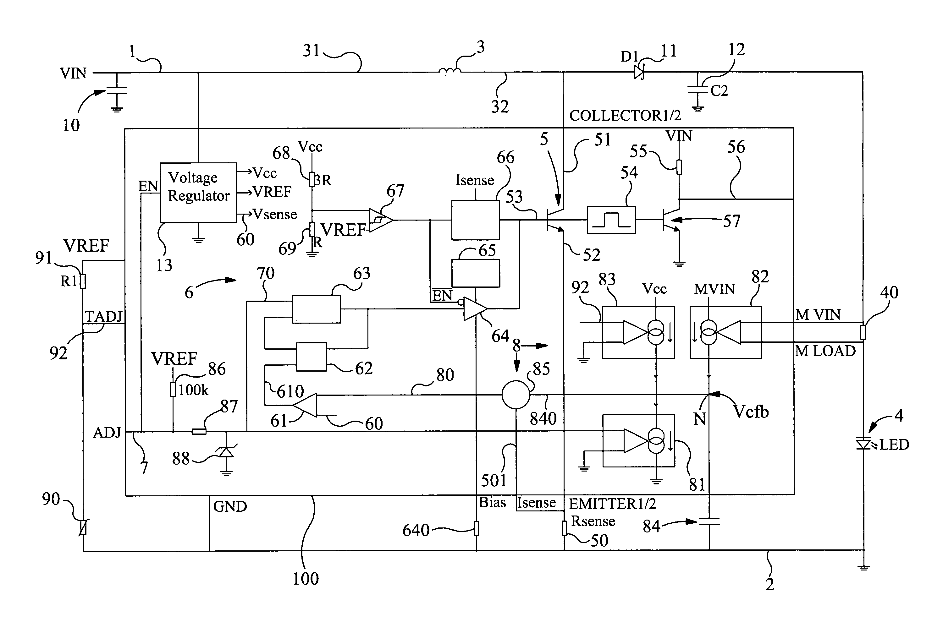
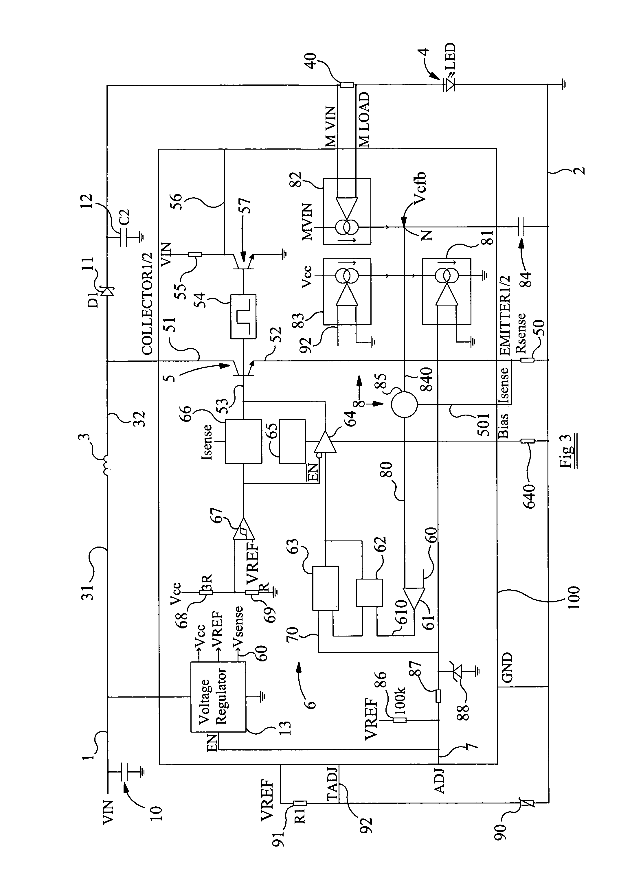
[0116]Referring now to FIG. 3, this shows a circuit embodying the invention, which can also be described as a drive circuit embodying the invention, arranged to drive a load 4. The circuit comprises a first supply rail 1 and a second supply rail 2 for connection to a dc power supply, providing a supply voltage Vin. An input capacitor 10 is connected between the supply voltage input and ground. An inductor 3 (L1) has a first inductor terminal 31 connected to the first supply rail 1, and has a second inductor terminal 32. A load 4 is connected in series with load current monitor resistor 40 (RM) between the second inductor terminal 32 and the second supply rail 2. In series with the load 4 is a diode 11, and an output capacitor 12 is connected in parallel with the load and RM, between the diode 11 and ground. In this embodiment the load 4 is a 3 W LED. The circuit also comprises a controllable switching device, in the form of a bipolar transistor 5, and a switching device current sens...


PUM


Abstract

A circuit comprises an inductor, a load, and a controllable switching device arranged in either a first configuration: switchable between the load being bypassed and the inductor energised, and current flowing through the load, and the inductor discharging energy into the load; or, a second configuration: switchable between current being permitted to flow through the load, inductor and controllable switching device in series, energising the inductor, and the current flowing through the load, and the inductor discharging energy into the load. The circuit further comprises control means for controlling the switching device, a load current sensing resistor connected in series with the load, and a demand signal input. Monitoring means is arranged to monitor the demand signal and the voltages across the sense resistors, and generate a monitor signal. The control means is arranged to receive the monitor signal and to switch the switching device in response the monitor signal exceeding a predetermined threshold.

Description

FIELD OF THE INVENTION[0001]The present invention relates to methods of driving a current through a load, and to circuits in which a current is driven through a load. In particular, although not exclusively, embodiments of the invention relate to the controlled driving of LEDs.BACKGROUND TO THE INVENTION[0002]For a variety of applications there is a requirement for a drive circuit able to provide regulated drive of a load from some dc power supply. One such drive circuit in accordance with the prior art is shown in FIG. 1 and incorporates a Zetex Semiconductors plc. voltage mode boost converter ZXSC410. The circuit may, for example, be connected to a battery power supply and is able to provide a regulated output voltage Vout to drive an attached load. Applications of the circuit include the provision of system power for battery-operated portable products, the biasing of LCDs, and local voltage conversion. Further details of the converter device are shown in FIG. 2. Operation of the ...

Claims


Application Information

Patent Timeline
Patent Type & Authority Patents(United States)
IPC IPC(8): G05F1/00H05B44/00
CPCH05B33/0815H02M3/156H05B45/3725H05B45/395Y02B20/30G05F1/62H05B45/00
Inventor TAYLOR, CRAIGMASON, HOWARD
Owner ZETEX SEMICON PLC
Why Eureka
Try Eureka