
Method of forming two-dimensional sheet material into three-dimensional structure

a technology of two-dimensional sheet material and three-dimensional structure, which is applied in the direction of forging/pressing/hammering equipment, paper/cardboard containers, handling devices, etc., can solve the problems of electromagnetic wave or radio frequency signal noise leakage out of the structure, reduce the strength of the folded structure, and increase the risk of damag

Inactive Publication Date: 2013-05-14
IND ORIGAMI INC CA US
View PDF438 Cites 30 Cited by
  • Summary
  • Abstract
  • Description
  • Claims
  • Application Information

AI Technical Summary

Benefits of technology

This approach minimizes gap areas, improves structural integrity, and reduces electromagnetic interference, while allowing for precise bending and secure formation of three-dimensional objects without the need for additional fasteners.

Problems solved by technology

As another example, the gaps may result from an engineered design to provide clearance during bending or lower manufacturing tolerances.
In yet another example, the gaps may be undesired, and may have resulted from various factors.
The presence of such gaps along the folded edges may present problems.
While there is considerable advantage to slit-forming or groove-forming techniques, in applications where shielding is important, gaps along the enclosure edges may lead to electromagnetic (“EM”) waves or radio-frequency (“RF”) signal noise leakage out of the structure.
Additionally, the presence of gaps or pockets along the bend lines may, in some instances, reduce the strength of the folded structure.

Method used


Image

  • Method of forming two-dimensional sheet material into three-dimensional structure
  • Method of forming two-dimensional sheet material into three-dimensional structure
  • Method of forming two-dimensional sheet material into three-dimensional structure

Examples


Embodiment Construction

[0037]Reference will now be made in detail to various exemplary embodiments of the present invention(s), examples of which are illustrated in the accompanying drawings and described below. While the invention(s) will be described in conjunction with exemplary embodiments, it will be understood that the present description is not intended to limit the invention(s) to those exemplary embodiments. On the contrary, the invention(s) is / are intended to cover not only the exemplary embodiments, but also various alternatives, modifications, equivalents and other exemplary embodiments, which may be included within the spirit and scope of the invention as defined by the appended claims.

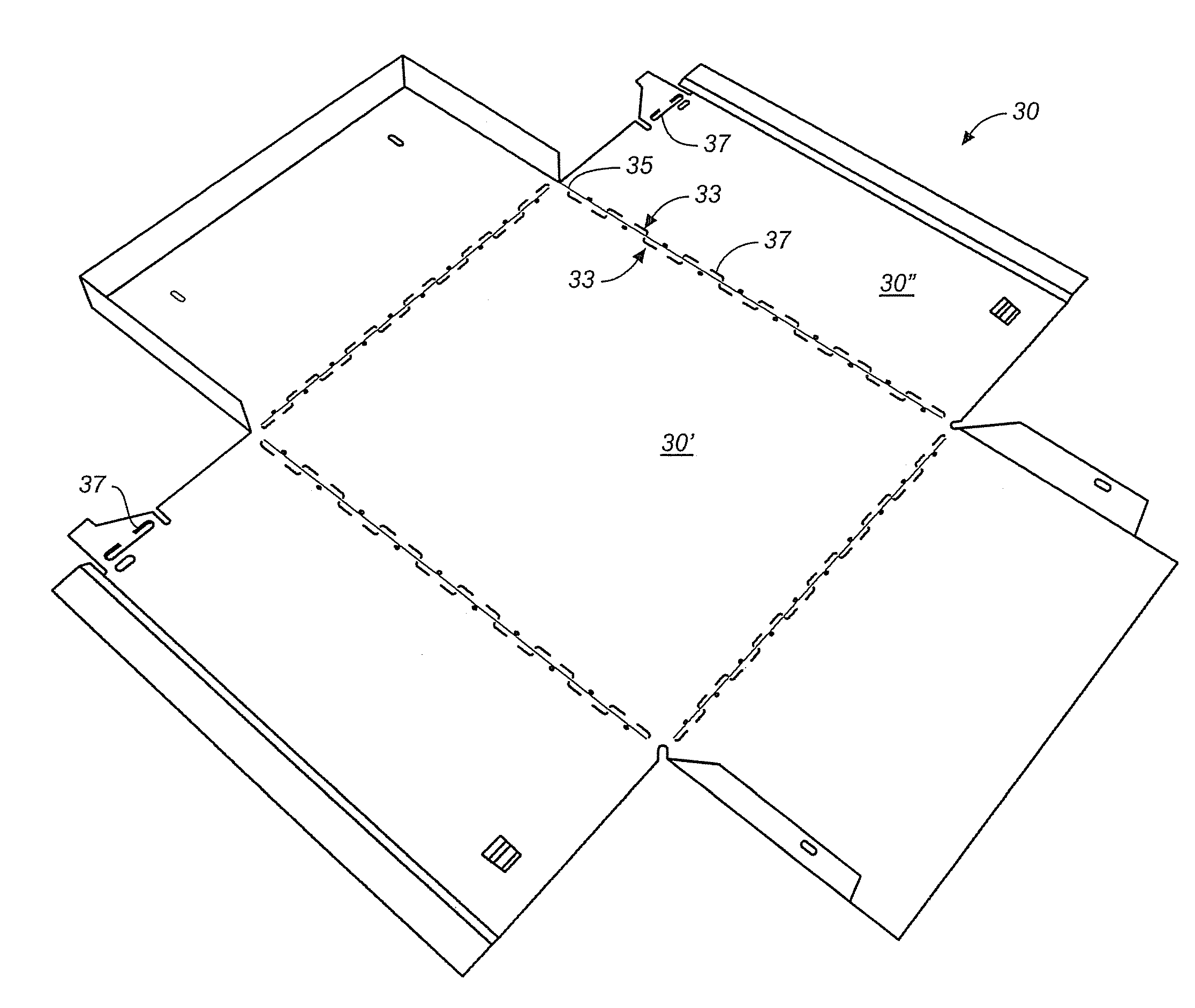
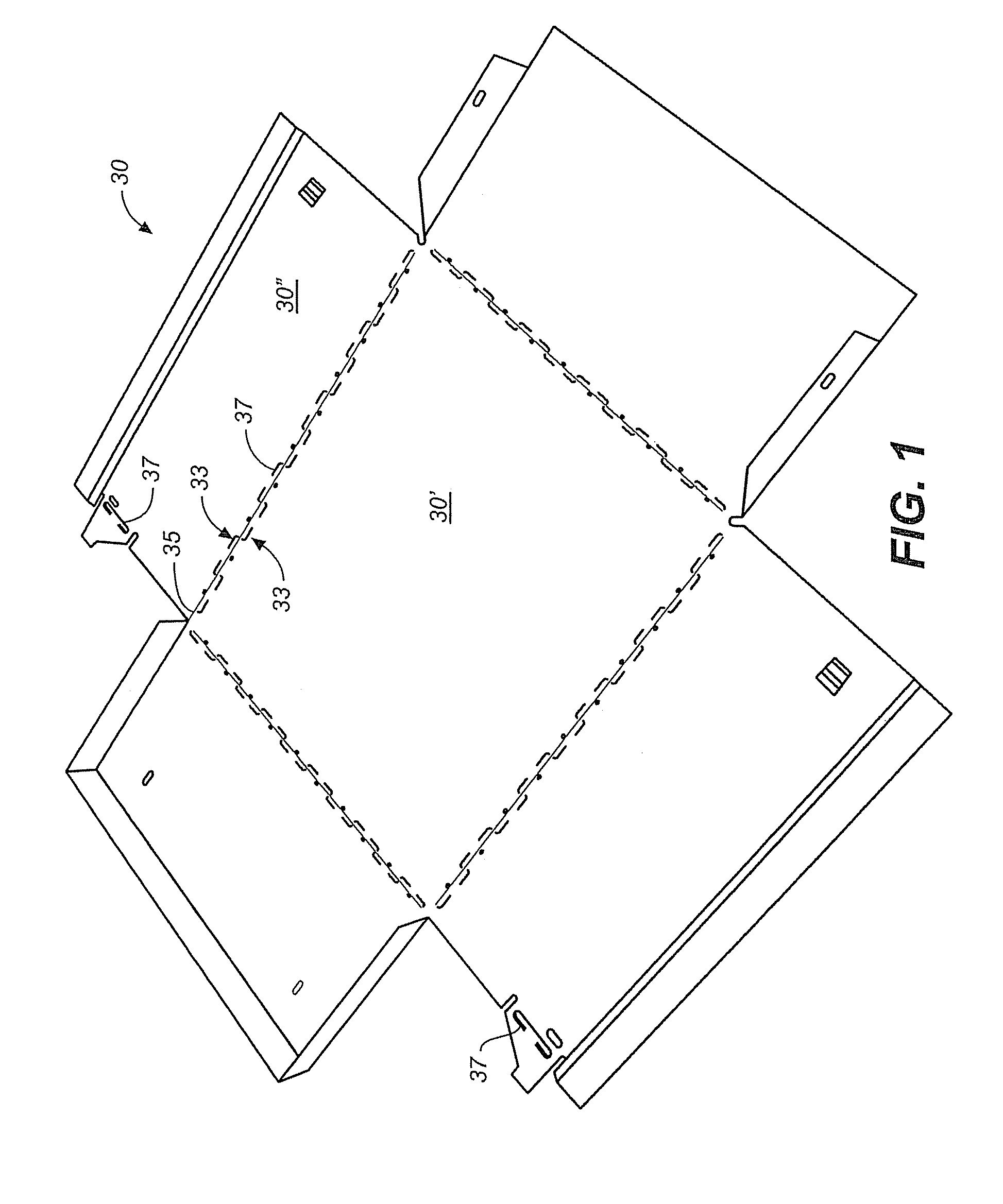
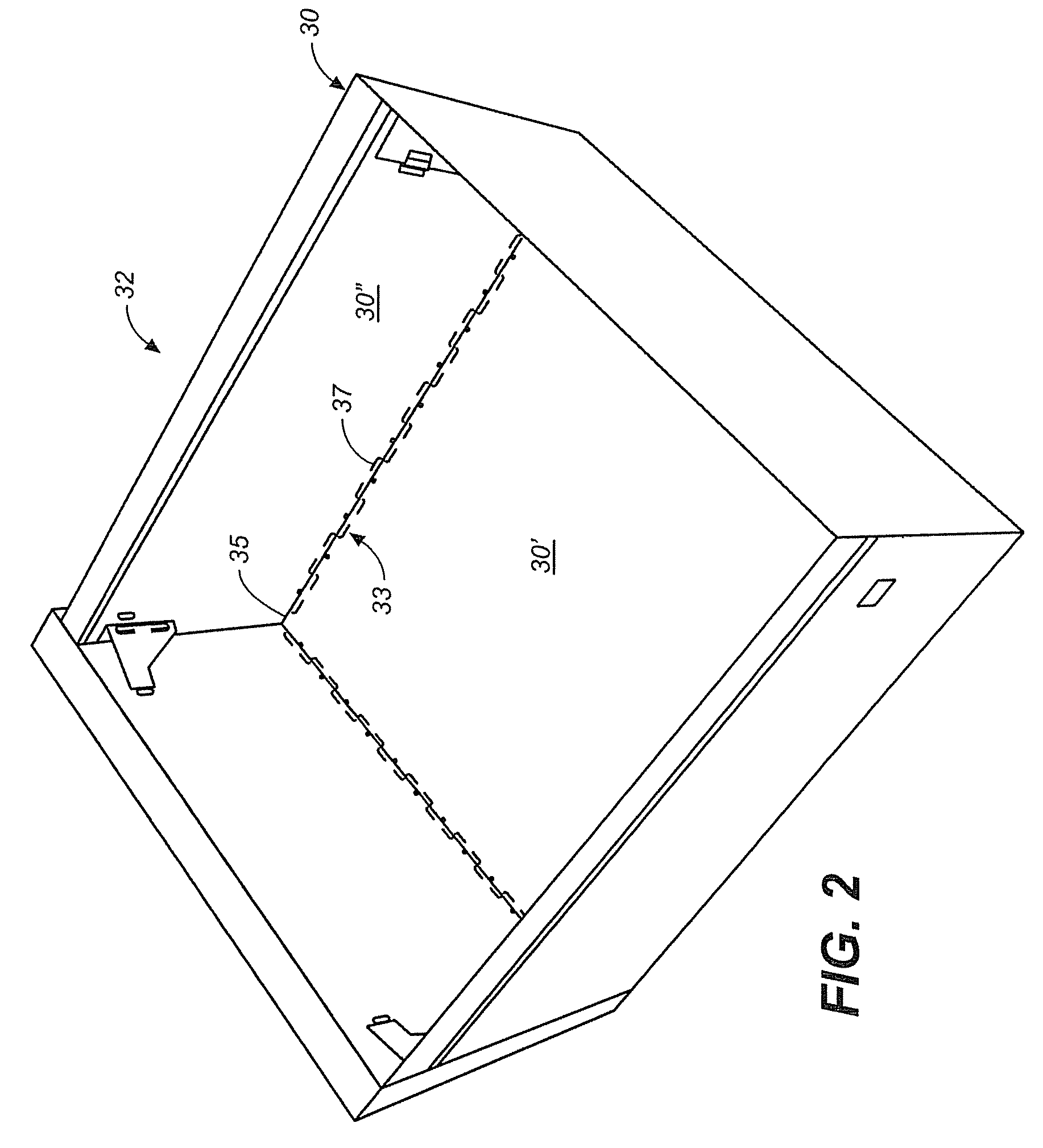
[0038]Turning now to the drawings, wherein like components are designated by like reference numerals throughout the various figures, attention is directed to FIG. 1 and FIG. 2 which disclose an exemplary two-dimensional (2D) sheet material 30 that has been dimensioned and configured to form a three-dimensional ...


PUM

PropertyMeasurementUnit
shieldingaaaaaaaaaa
radio-frequencyaaaaaaaaaa
surface areaaaaaaaaaaa

Abstract

A two-dimensional sheet material is provided that is suitable for bending along a bend line to form a three-dimensional object. The sheet material is provided with a plurality of displacements in a thickness direction of the sheet material on one side of the bend line. A portion of the displacements shear adjacent the bend line and define an edge and an opposed face. The edge and opposed face configured to produce edge-to-face engagement of the sheet material during bending. Alternatively, sheet material is provided with a plurality of displacements in a thickness direction of the sheet material on one or both sides of the bend line, and with a plurality of corresponding and cooperating protrusions to improve structural integrity and / or to improve electromagnetic and radio frequency shielding. The sheet material may also be provided with a self-latching structure. A method of preparing and using these sheet materials is also described.

Description

CROSS-REFERENCES TO RELATED APPLICATIONS[0001]This application is a Divisional of U.S. patent application Ser. No. 11 / 925,195, filed Oct. 26, 2007, and entitled METHOD OF FORMING TWO-DIMENSIONAL SHEET MATERIAL INTO THREE-DIMENSIONAL STRUCTURE, which claims priority to U.S. Provisional Patent Application No. 60 / 854,846, filed Oct. 26, 2006, and entitled SHEET MATERIAL WITH BEND CONTROLLING DISPLACEMENTS, and to U.S. Provisional Patent Application No. 60 / 974,473, filed Sep. 23, 2007, and entitled METHOD OF FORMING TWO-DIMENSIONAL SHEET MATERIAL INTO THREE-DIMENSIONAL STRUCTURE, the entire contents of which applications is incorporated herein by this reference.BACKGROUND OF THE INVENTION[0002]1. Field of the Invention[0003]This invention relates, in general, to preparing sheets of material for bending using punching, stamping, roll-forming, and similar processes and then bending the sheets into three-dimensional structures.[0004]2. Description of Related Art[0005]Various methods of pre...

Claims


Application Information

Patent Timeline
Patent Type & Authority Patents(United States)
IPC IPC(8): B21D43/28
CPCB21D5/00B21D51/52B65D7/08B21D39/03
Inventor DURNEY, MAX W.VAIDYANATHAN, RADHALAM, RYAN
Owner IND ORIGAMI INC CA US
Learn More