
Marine drive shift control system

a shift control and driveline technology, applied in the field of marine drives, can solve the problems of engine stalling and increased wear on major driveline components

Active Publication Date: 2013-05-14
BRUNSWICK CORPORATION
View PDF8 Cites 28 Cited by
  • Summary
  • Abstract
  • Description
  • Claims
  • Application Information

AI Technical Summary

Benefits of technology

The invention relates to a system for controlling shifts in marine drives. When shifting from forward to reverse, there is a sudden drop in engine speed which causes a high rotational speed difference in the clutch mechanism of the transmission. This can result in engine stalling and damage to the drive system components. Current methods use full gear pressure during clutch engagement, regardless of vessel or propeller speeds. The present invention provides a solution to this problem by allowing for slip during clutch engagement to prevent damage to the drive system.

Problems solved by technology

The action of closing the reverse clutch under full pressure at these high rotational speed differences can cause engine stalling and increased wear on major driveline components.

Method used


Image

  • Marine drive shift control system
  • Marine drive shift control system

Examples


Embodiment Construction

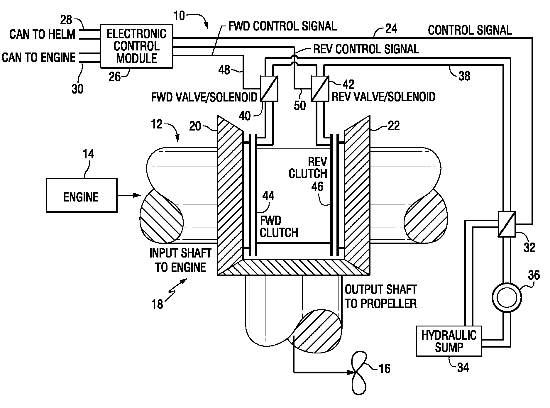
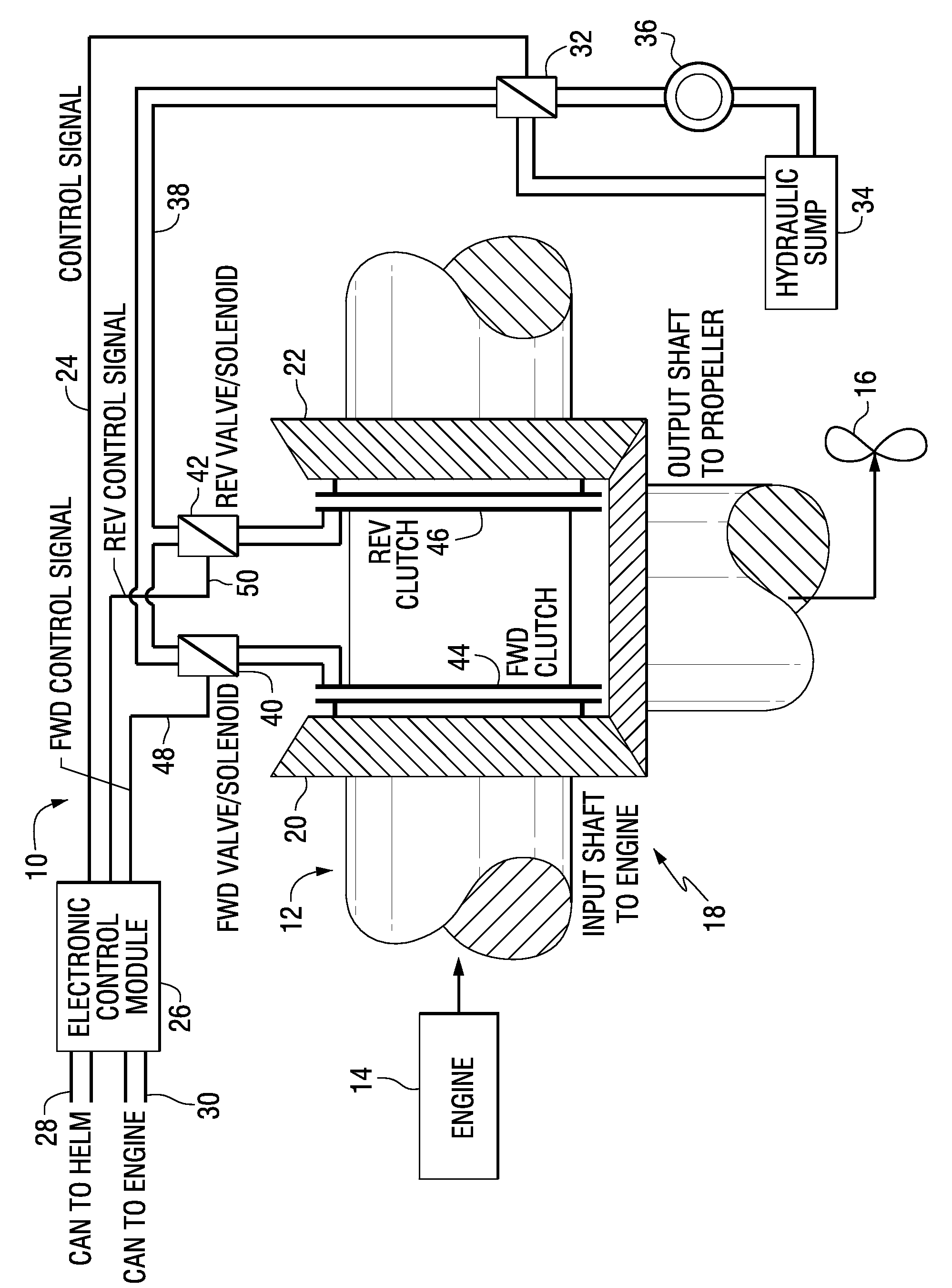
[0005]FIG. 1 shows a shift controller 10 for a marine drive 12 having an internal combustion engine 14 driving a propulsor such as propeller 16 through a transmission 18 shiftable between forward and reverse gears 20 and 22, respectively, as is known. In one embodiment, the shift controller uses the troll control signal at 24 from ECM (electronic control module) 26 which communicates with the helm and the engine via respective CAN buses 28 and 30, as is known, which troll control signal at 24 controls valve / solenoid 32 to supply hydraulic fluid from sump 34 and pump 36 at supply line 38 to apply limited hydraulic clutch pressure in forward and / or reverse through respective forward and reverse valve / solenoids 40 and 42 to respective forward and reverse clutches 44 and 46 as controlled by respective forward and reverse control signals at 48 and 50 from ECM 26, as is known.

[0006]In the present system, the noted shift controller is also used to apply partial clutch engagement pressure u...


PUM


Abstract

A shift control system for a marine drive applies partial clutch engagement pressure upon initial shifting from forward to reverse to prevent stalling of the engine otherwise caused by applying full clutch engagement pressure upon shifting from forward to reverse.

Description

BACKGROUND AND SUMMARY[0001]The invention relates to marine drives, and more particularly to a marine drive shift control system.[0002]Marine drives typically have an internal combustion engine driving a propulsor through a transmission shiftable between forward and reverse in clutched engagement with forward and reverse gears, respectively. When the transmission is shifted from forward gear, particularly wide open throttle, to reverse gear, engine speed drops significantly more quickly than vessel over water speed. The latter is directly proportional to the propeller speed when free wheeling in neutral gear. The difference in engine speed (and consequently transmission input speed) and the vessel over water speed (and consequently propeller speed and transmission output speed) causes a high rotational speed difference (e.g. up to 2,000 rpm) in the clutch mechanism of the transmission during entry into reverse gear. The action of closing the reverse clutch under full pressure at the...

Claims


Application Information

Patent Timeline
IPC IPC(8): B60W10/00
CPCF16H61/0246B63H23/08B60W30/18045Y10T477/6403Y10T477/78
Inventor BAZAN, ANDREW H.MILLER, KYLE M.SAMPLES, WILLIAM J.WHITTINGTON, JR., DOYLE E.LIANG, CHIH-HUA
Owner BRUNSWICK CORPORATION
Learn More