Negative pressure bandage with internal storage chamber

Inactive Publication Date: 2013-05-14
MILLER LARRY W
View PDF7 Cites 42 Cited by
  • Summary
  • Abstract
  • Description
  • Claims
  • Application Information

AI Technical Summary

Benefits of technology

[0018]It is still a further object of this invention to provide a negative pressure bandage utilizing a two chamber configuration, which is durable in construction, inexpensive of manufacture, carefree of maintenance, facile in assemblage, and simple and effective in use.
[0019]These and other objects, features and advantages are accomplished according to the instant invention by providing a negative pressure bandage formed in a two chamber configuration having a lower chamber from which fluids and exudates are collected from an open wound on the patient and an upper chamber that is used to store the collected fluids and exuda

Problems solved by technology

Conventional negative pressure bandages are generally large in size and often require the use of complicated equipment such as suction pumps, vacuum pumps and complex electronic controllers to apply a negative

Method used


Image

  • Negative pressure bandage with internal storage chamber
  • Negative pressure bandage with internal storage chamber
  • Negative pressure bandage with internal storage chamber

Examples


Embodiment Construction

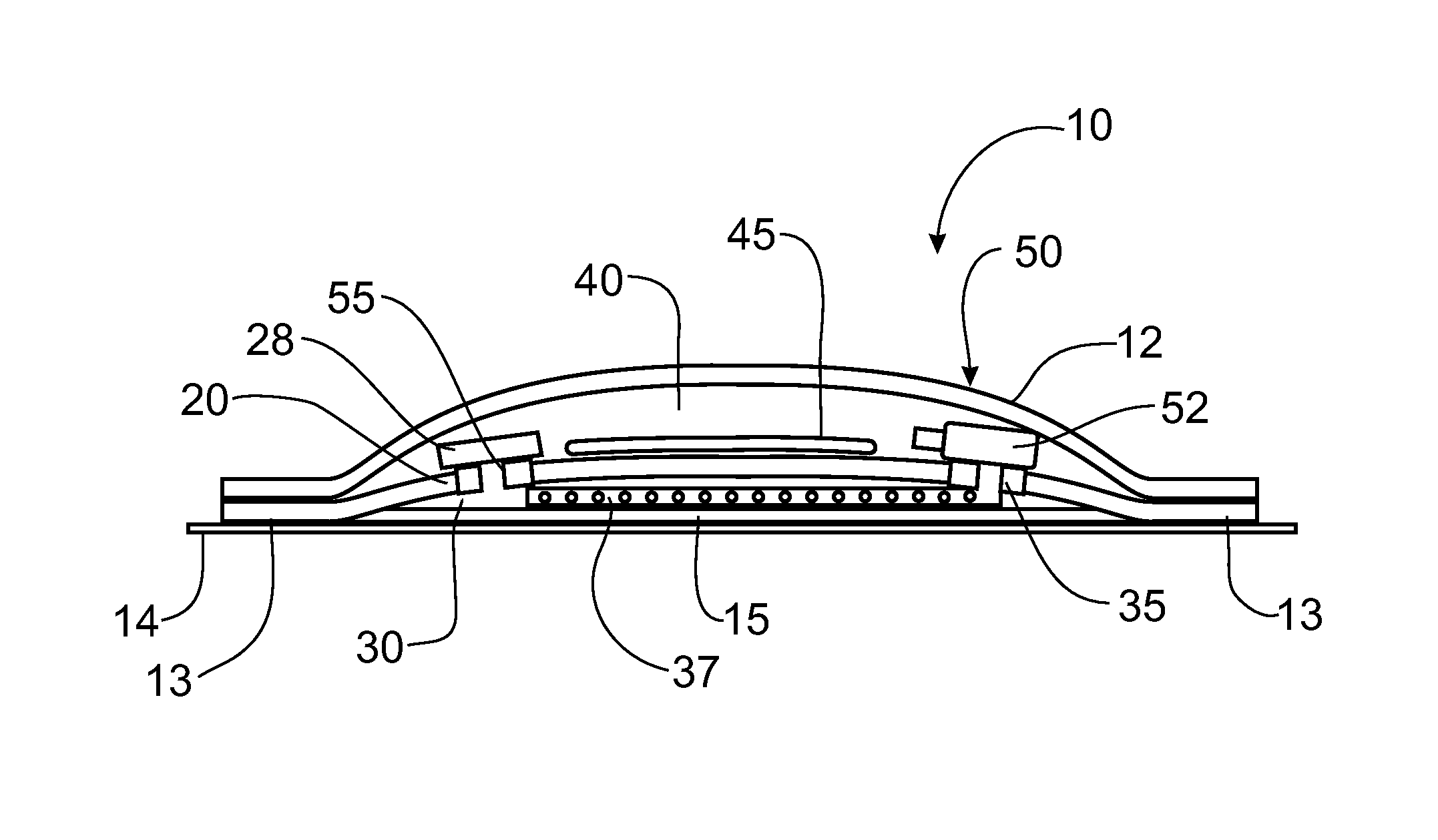
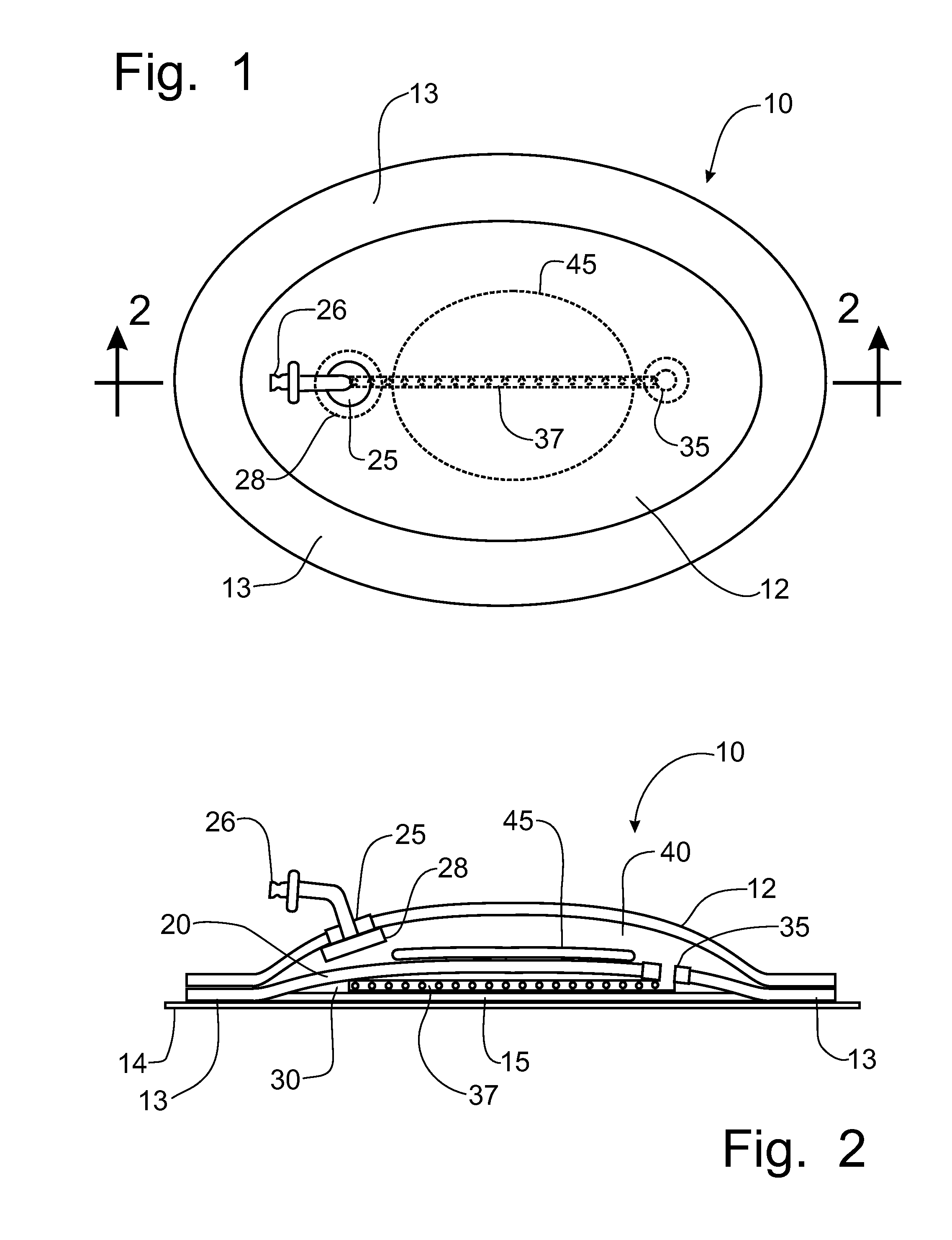
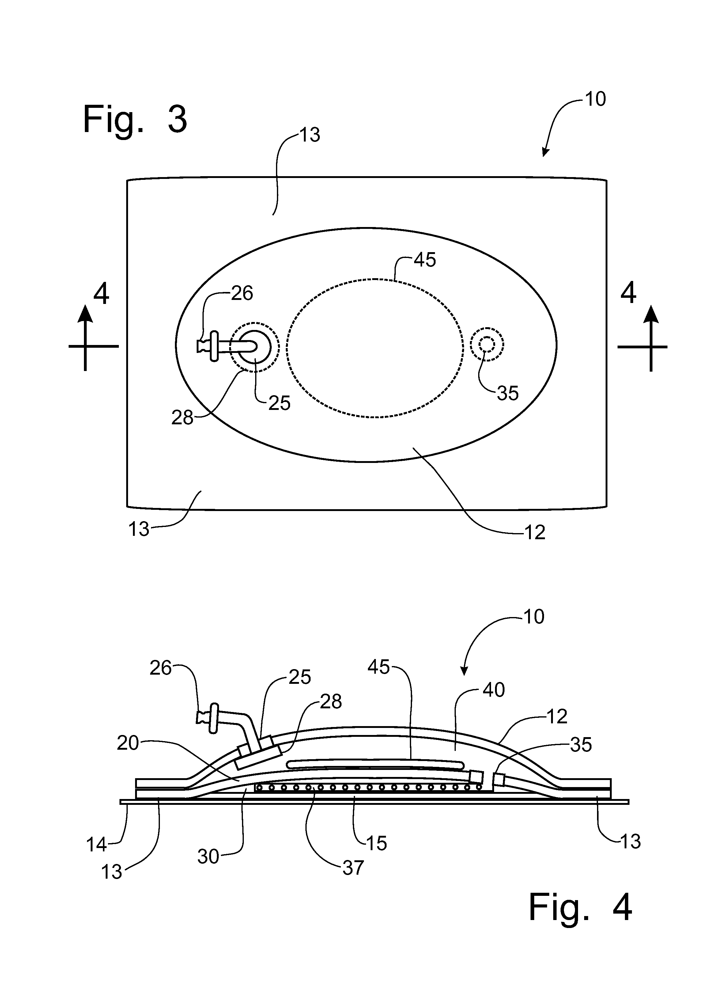
[0034]Referring to the drawings, a negative pressure bandage incorporating the principles of the instant invention can best be seen. The negative pressure bandage 10 has an outer housing 12 that is exposed outwardly from the patient when the bandage 10 is applied to an open wound to remove the exudates and fluids therefrom when connected to a conventional vacuum source (not shown). The outer housing 12 can be formed in any suitable shape, including an oval shape as shown in FIG. 1 or a rectangular shape as depicted in FIG. 3. The vacuum source (not shown) is typically a small pump that is worn by the patient remotely from the bandage 10 to apply a vacuum to the bandage 10 and affect the removal of exudates and fluids from the wound site through conventional tubing (not shown) that is connected to the bandage 10, as will be described in greater detail below.

[0035]The bandage 10 has a wound contact panel 15 below the outer housing 12. The wound contact panel 15 can be a layer of gauze...


PUM


Abstract

A negative pressure bandage is formed in a two chamber configuration having a lower chamber from which fluids and exudates are collected from an open wound on the patient and an upper chamber that is used to store the collected fluids and exudates removed by an application of a vacuum to the lower chamber. An impermeable layer separates the upper and lower chambers to keep the wound dry and promote healing. A vacuum port interconnects a fluid collection member located in the lower chamber with the upper chamber to allow the application of a vacuum that collects and removes fluids and exudates from the lower chamber. The vacuum pump can be remote and attached to the bandage by tubing or be incorporated into the bandage to provide a self-contained negative pressure bandage. An absorptive pad can be located in the upper chamber to collect and gel the collected fluids.

Description

FIELD OF THE INVENTION[0001]The present invention relates generally to negative pressure bandages operable to remove exudates and fluids from a wound and, more particularly, to a bandage structure that has a lower chamber for collecting the exudates and fluid for removal to a secondary bladder above the collection chamber, but within the structure of the bandage.BACKGROUND OF THE INVENTION[0002]Negative pressure therapy has been utilized for the treatment of a variety of wounds by medical practitioners. Conventional negative pressure bandages are generally large in size and often require the use of complicated equipment such as suction pumps, vacuum pumps and complex electronic controllers to apply a negative pressure within the bandage to draw exudates and fluids away from the wound to a remote collection container. Typically, negative pressure therapy involves other associated equipment, such as the exudates / fluid collection canisters, liquid transporting conduits, and pressure re...

Claims


Application Information

Patent Timeline
IPC IPC(8): A61M1/00A61M27/00
CPCA61F13/00068A61F13/0216A61M1/0088A61M1/009A61M1/962A61M1/915A61M1/984A61M1/985
Inventor MILLER, LARRY W.
Owner MILLER LARRY W
Why Eureka
Try Eureka