Sensing circuit

a technology of sensing circuit and circuit board, which is applied in the direction of fuses testing, instruments, alarms, etc., can solve the problems of imposing a significant current drain, and the use of electrically programmable fuses in modern integrated circuits

Active Publication Date: 2013-05-14
ALTERA CORP
View PDF5 Cites 17 Cited by
  • Summary
  • Abstract
  • Description
  • Claims
  • Application Information

AI Technical Summary

Benefits of technology

[0007]The invention may be practiced with any type of fuse including those that are laser programmable such as metal fuses and those that are electrically programmable such as polysilicon (poly) fuses. The invention may also be used to compare the resistance of other circuit elements with the reference resistance and, in general, to compare the resistance of a device under test (DUT) with the reference resistance.

Problems solved by technology

It has been difficult, however, to use electrically programmable fuses in modern integrated circuits because the fuses use a bias voltage that requires them to be relatively large in size and they have a narrow window of sensitivity that does not work well across process, voltage and temperature variations.
As a result, in an integrated circuit with a large number of fuses, the use of circuits such as that of the '527 patent to sense the fuses imposes a significant current drain.

Method used


Image

  • Sensing circuit
  • Sensing circuit
  • Sensing circuit

Examples


Embodiment Construction

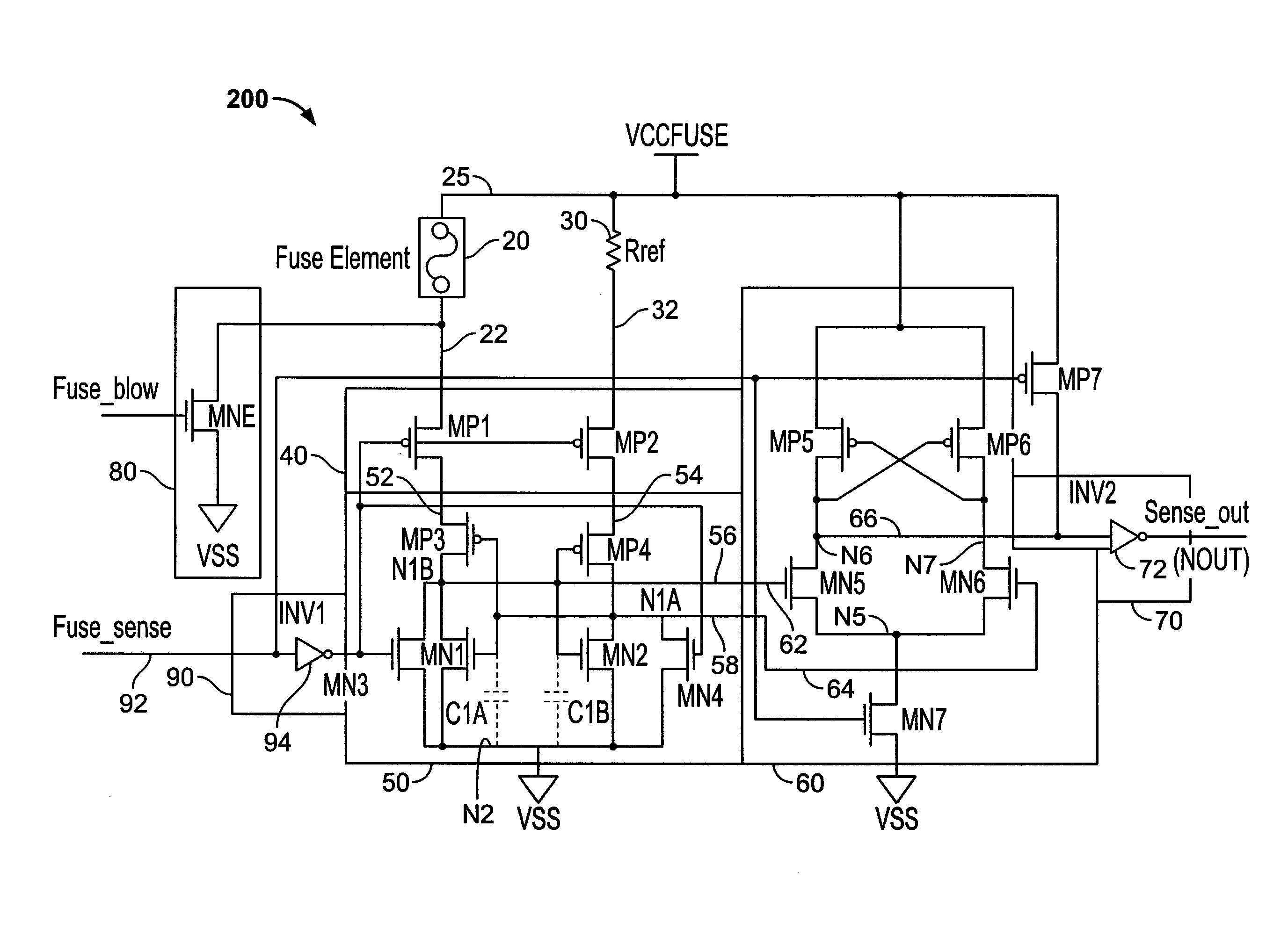
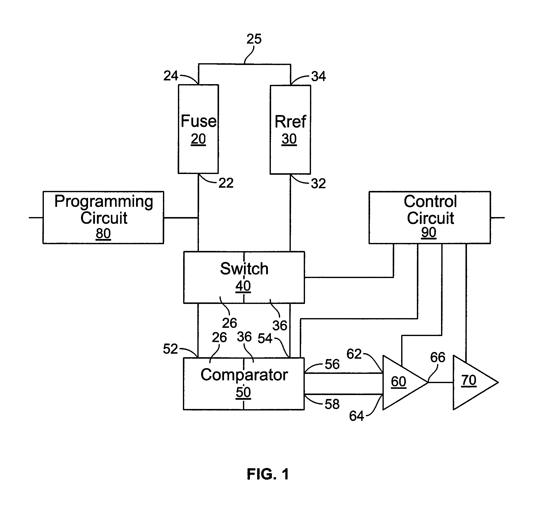
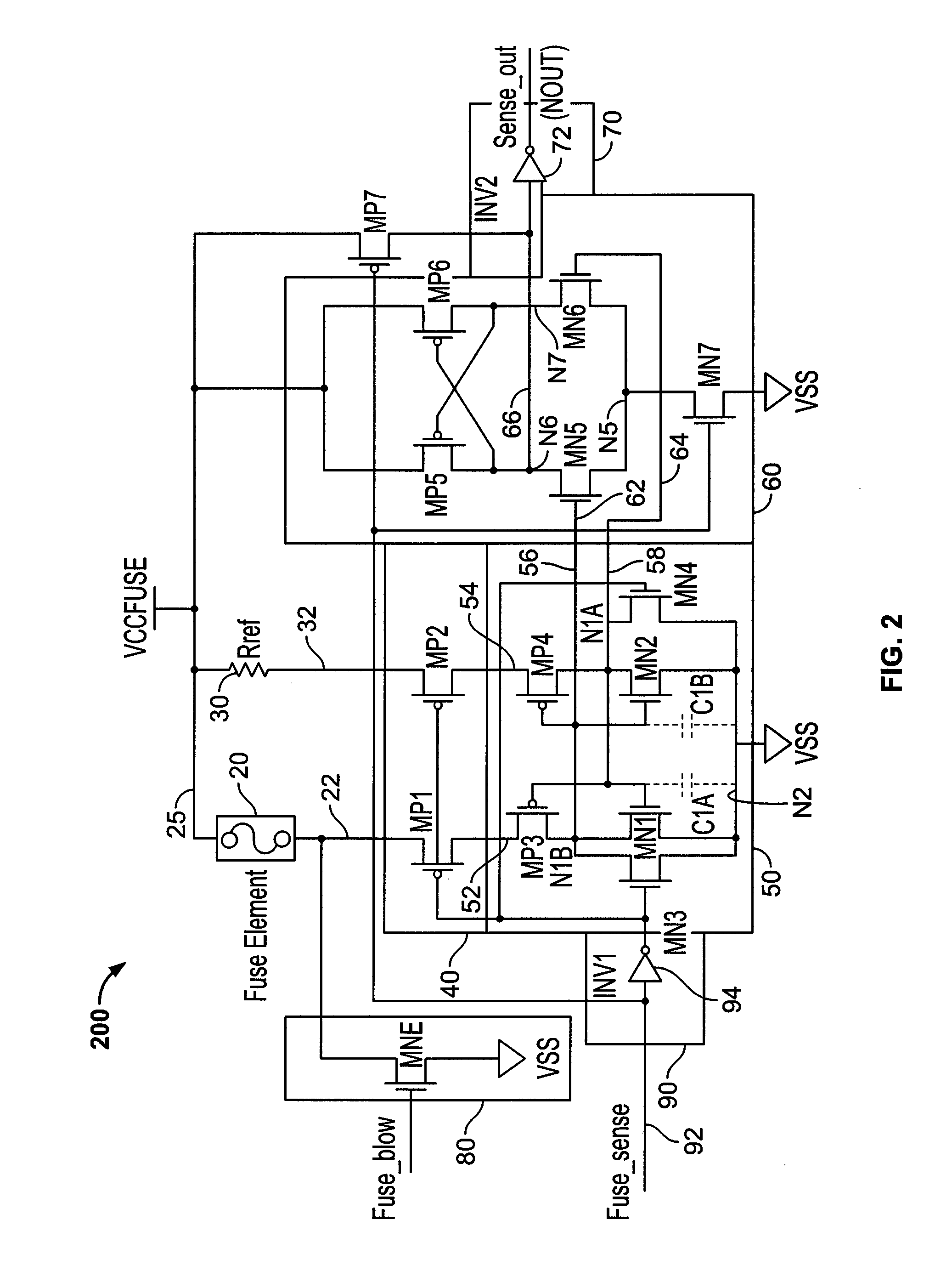
[0012]FIG. 1 is block diagram of an illustrative sensing circuit 10 of the present invention. Circuit 10 comprises a fuse 20, a reference resistance 30, a switch 40, a comparator 50, an amplifier 60, and an output buffer 70. Circuit 10 further comprises a programming circuit 80 for programming fuse 20 and a control circuit 90 for controlling switch 40, comparator 50, amplifier 60 and output buffer 70. In the case where fuse 20 is a polysilicon (or poly) fuse or a copper fuse, the resistance of the fuse in its unprogrammed state is typically in the range of 100 to 200 Ohms. In its programmed state, the minimum resistance of the fuse is typically in the range of 2,000 to 10,000 Ohms. For these resistance values for fuse 20, a typical resistance value for resistance 30 is approximately 900 Ohms.

[0013]Comparator 50 has first and second inputs 52, 54 and first and second outputs 56, 58; and amplifier 60 has first and second inputs 62, 64 and at least a first output 66. The first and seco...


PUM


Abstract

A sensing circuit for comparing current flow through a reference resistance with current flow through a resistive device under test (DUT) such as a fuse. The sensing circuit includes a comparator having a first PMOS transistor and a first NMOS transistor connected in series between a first input and a first node and a second PMOS transistor and a second NMOS transistor connected in series between a second input and the first node. The first PMOS and NMOS transistors are cross-coupled with the second PMOS and NMOS transistors. Specifically, a first output is connected to the first node to the gates of the second PMOS and second NMOS transistors and a second output is connected to the second node and to the gates of the first PMOS and first NMOS transistors. The reference resistance is connected to one of the inputs and the DUT is connected to the other input.

Description

FIELD OF THE INVENTION[0001]This relates to a sensing circuit. This circuit was developed to address problems encountered in sensing a programmed state of fuses such as polysilicon or copper fuses and will be described in that context. However, this circuit also has applications in sensing other devices under test.BACKGROUND OF THE INVENTION[0002]Fuses are widely used in semiconductor integrated circuits in both analog and digital circuits. For example, they can be used to store security codes, manufacturing data, device dependent data, redundant data, etc. A conventional integrated circuit might have 1000 or more fuses in its circuitry. Early fuses were metal based and were programmed by destroying the fuse with a laser beam. More recently, fuses have been developed that are electrically programmable using electromigration. See, for example, C. Kothandaraman et al., “Electrically Programmable Fuse (eFuse) Using Electromigration in Silicides,” IEEE Electron Device Letters, Vol. 23, ...

Claims


Application Information

Patent Timeline
Patent Type & Authority Patents(United States)
IPC IPC(8): H01H85/30G01R31/02G08B21/00
CPCG11C17/18G01R31/07G11C29/50008G11C7/062G11C29/027G11C17/16G01R31/74
Inventor XIAO, PINGDING, WEIYING
Owner ALTERA CORP
Why Eureka
Try Eureka