Sliding door

a sliding door and door technology, applied in the field of sliding doors, can solve the problems of easy damage to glass doors, damage to doors such as glass doors,

Inactive Publication Date: 2013-05-21
DORMAKABA DEUT GMBH
View PDF31 Cites 8 Cited by
  • Summary
  • Abstract
  • Description
  • Claims
  • Application Information

AI Technical Summary

Benefits of technology

[0006]It is an object of the invention to provide a sliding door, in which a closing device achieves a displacement into a terminal position and simultaneously a dampening effect for both, the opening procedure and the closing procedure. In this case, the closing device is preferably as compact as possible and should be retrofittable to existing sliding doors.
[0007]According to one embodiment of the invention, the closing device is disposed at or in the carrier of the carriage. This disposition type of the closing device at or in the carrier of the carriage results in the closing device being moved with the door leaf and being able to be disposed within the profiles. Thus a visually appealing and compact solution can be achieved, in which the closing device is not visible for the user of the sliding door.
[0008]One advantageous embodiment of the invention results from a spring-dampening element being utilized as the closing device, which can be inexpensively purchased as a standard structural component.
[0010]In a preferred embodiment, one or more adhesive adapters, which are glued to the border area of the door leaf, are utilized as the attachment. The advantage is that the integrity of the door leaf is maintained. In particular with glass doors, the advantage is that expensive and complicated boring can be foregone, which otherwise would introduce tensions into the glass which frequently result in breaking of glass on the construction site. The previous attachment of fittings or roller carriages at glass panes of undampened doors requires large glue surfaces, because the stop impulse that pulls on the glue location, sooner or later results in failure of the glue location. Equipping a sliding door with a dampened closing device reduces the stop impulse, such that the glue surfaces of the fittings can be smaller and do not fail any more. Due to the inventive combination of a dampened closing device with adhesive fittings, very compact carriages can be realized, in which the glass door does not require any bores and the fittings are invisible to the user.
[0011]In another embodiment, the carrying rollers of the carriages are disposed at opposite ends of the carrier, such that—in combination with the easy rotating self-adjustment between carriage and door leaf—roller unevenness can be compensated. The door moves smoothly and straight.

Problems solved by technology

The problem with sliding doors is that very often the doors, when being carelessly opened or closed, impact on an end stop; this can be very loud and can also destroy a door, such as a glass door.
If the sliding door is closed with too much force, it will often strike against the end stop which can only absorb a portion of the energy, such that the sliding door bounces back and remains in a not completely closed position.
When opening a sliding door with too much force, this results very often in the problem that, although the first user is able to easily pass the door, as he / she has triggered the opening procedure, the sliding door simultaneously returns into the partially closed position and the following user of the sliding door bounces against it with his shoulder or side; whereby on the one hand there is a risk of injury and, on the other hand, the sliding door will start to swing perpendicularly to the opening direction and thus may be prone to damage.

Method used


Image

  • Sliding door
  • Sliding door
  • Sliding door

Examples


Embodiment Construction

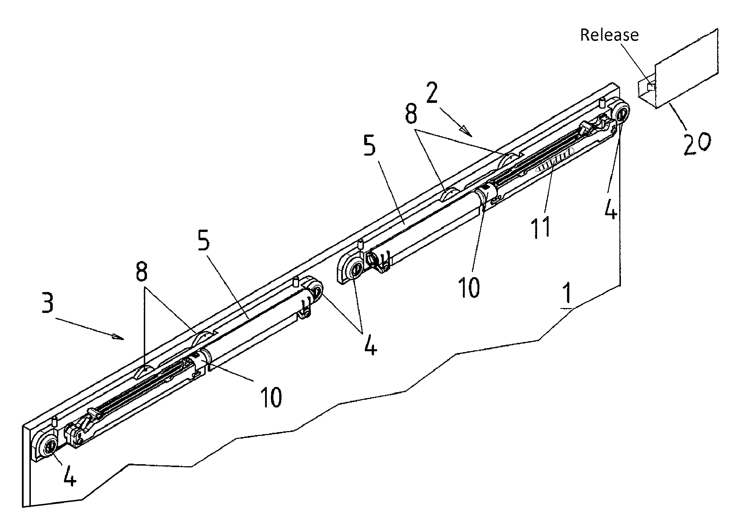
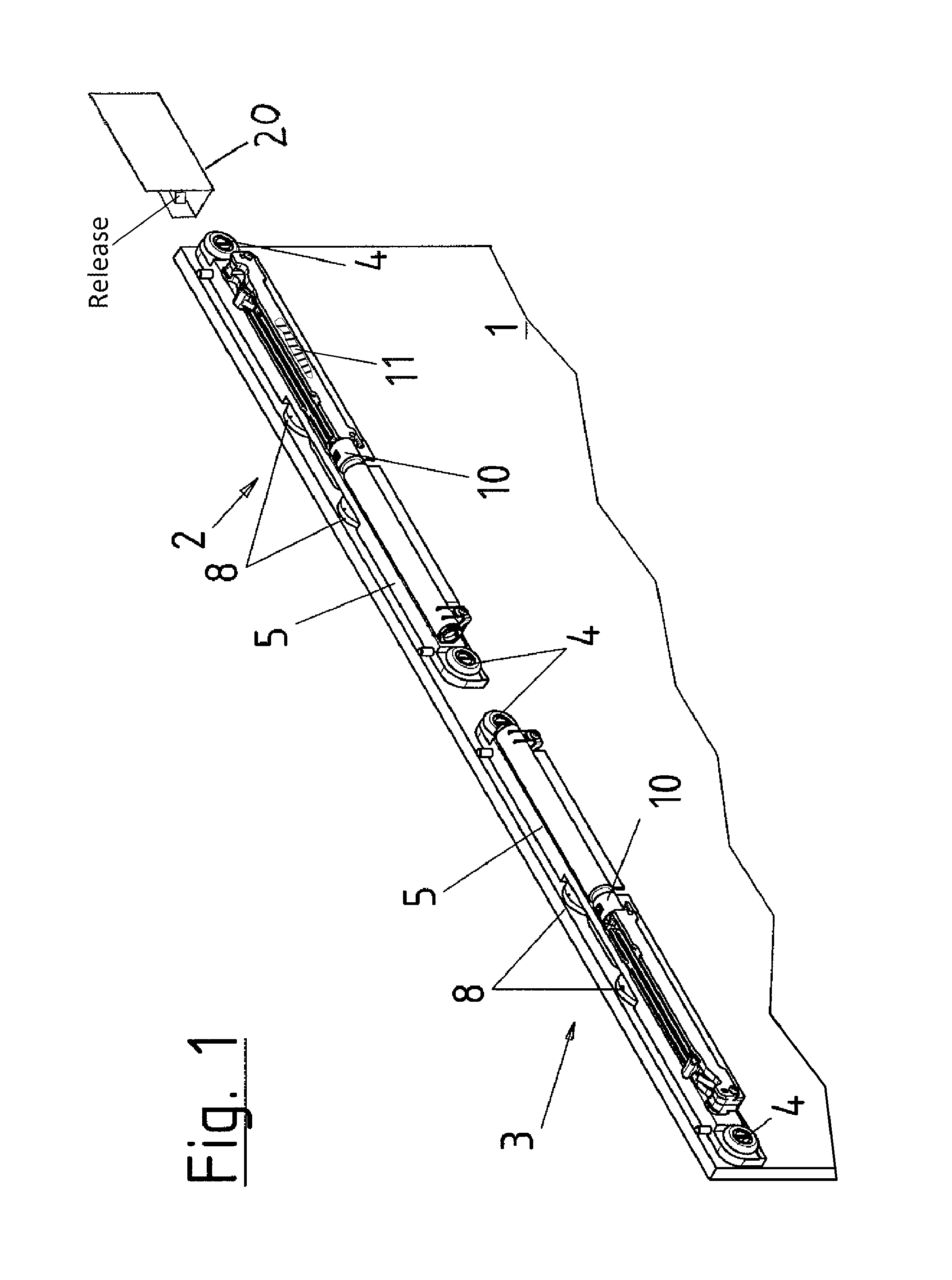
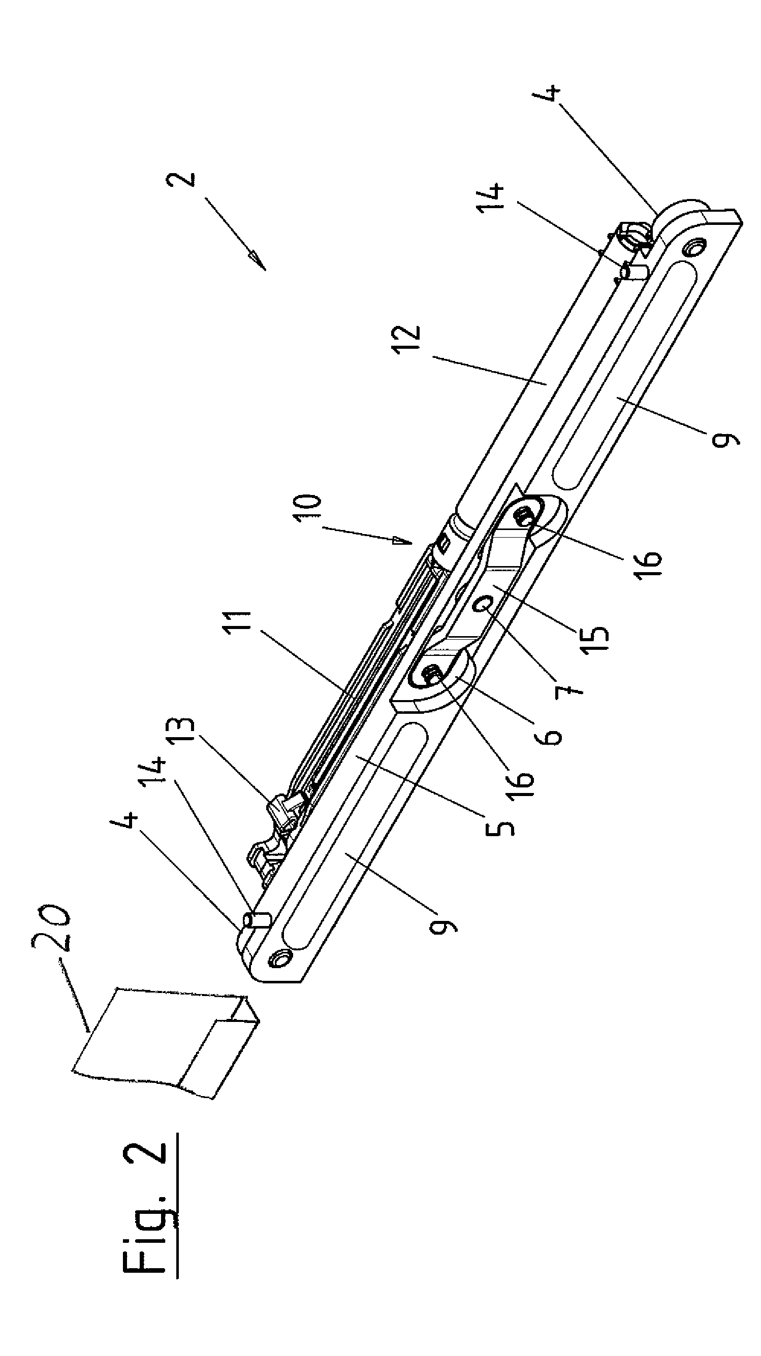
[0019]In FIG. 1, the inventive sliding door is illustrated which comprises a door leaf 1 with two carriages 2, 3. The carriages 2, 3 guide the door leaf 1 in a displaceable manner in a roller rail profile 20, wherein the roller rail profile is directly or indirectly attached to a wall or to a ceiling. The door leaf 1 may consist of glass, wood or another arbitrary material. Each carriage 2, 3 has a carrier 5, one carrying roller 4 each being disposed at the opposite ends of the carrier. In this case, the carrying rollers 4 are disposed for example in a depression at the carrier 5, such that the carrier 5 can be configured with a minimum depth.

[0020]The door leaf 1 is attached to the carrier 5 of the carriages 2, 3 by a clamping device or an attachment device. These devices may consist of a single point fixing, in which the clamping element engages in a bore of the door leaf 1 and clampingly retains the latter.

[0021]The attachment device may also consist of an adhesive adapter 8 atta...


PUM


Abstract

A sliding door with a door leaf, which is suspended from two carriages and displaceably guided along a roller rail profile, which is disposed at a wall or at a ceiling, the sliding door having at least one closing device, which is suitable to displace the decelerated door leaf into a closed position. The at least one carriage has a carrier, at or in which the closing device is disposed.

Description

BACKGROUND OF THE INVENTION[0001]1. Field of the Invention[0002]The present invention relates to a sliding door with a door leaf suspended from at least one carriage and displaceably guided along a roller rail profile disposed at a wall or at a ceiling. The sliding door includes a closing device, which is suitable to displace the decelerated door leaf into a closed position.[0003]2. Description of the Related Art[0004]The problem with sliding doors is that very often the doors, when being carelessly opened or closed, impact on an end stop; this can be very loud and can also destroy a door, such as a glass door. If the sliding door is closed with too much force, it will often strike against the end stop which can only absorb a portion of the energy, such that the sliding door bounces back and remains in a not completely closed position. Closing devices are known that displace the sliding door into a final position and simultaneously achieve a dampening effect.[0005]When opening a sli...

Claims


Application Information

Patent Timeline
Patent Type & Authority Patents(United States)
IPC IPC(8): E05F11/54E05F5/08E05F5/10
CPCE05F1/16E05F5/027Y10T16/56E05Y2900/132E05Y2600/46
Inventor WALHORN, OLIVER
Owner DORMAKABA DEUT GMBH
Why Eureka
Try Eureka